background image

Noraxon U.S.A., Inc. 


myoMOTION Data Logger 


P-6828 Rev A (Oct 2014)  


11

Component


Inputs,


Outputs


and


Indicators


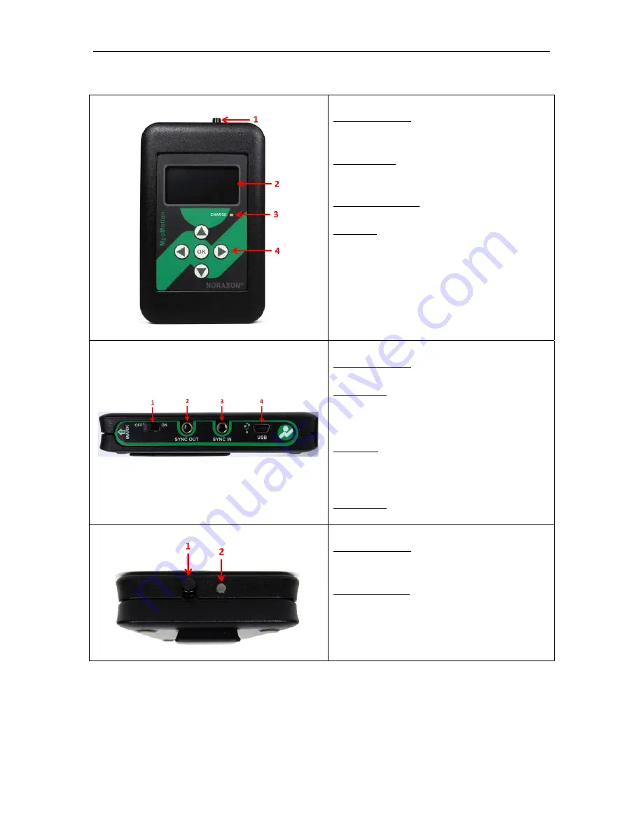
1A


Data


Logger


(Front)


1


Marker


Button


When


pressed,


this


button


creates


a


marker


in


the


record


that


can


later


be


used


in


the


analysis


2


LED


Display


Guides


the


user


through


the


setup


and


indicates


the


status


of


the


data


logger


i.e.


USB


Ready,


Measuring,


etc.


3


Charge


Indicator


–Illuminates


when


the


Data


Logger


is


charging


4


Keypad


Used


to


navigate


device


setup


and


begin


measurements


1B


Data


Logger


(Side)


1.


Power


Switch


Toggles


to


turn


the


Data


Logger


OFF


or


ON


2.


Sync


Out


TTL


(on

off)


compatible


3.5


mm


stereo


jack


connection


to


other


Noraxon


devices


used


to


send


a


sync


pulse


to


other


devices


3.


Sync


In


TTL


(on

off)


compatible


3.5


mm


stereo


jack


connection


to


other


Noraxon


devices


used


to


accept


a


sync


pulse


generated


by


other


devices


4.


USB


Port


Mini


B


style


USB


connection


1C


Data


Logger


(Top)


1


Marker


Button


When


pressed,


this


button


creates


a


marker


in


the


record


that


can


later


be


used


in


the


analysis


2


Light


Indicator


Illuminates


at


every


second


of


the


calibration


countdown


Summary of Contents for myoMOTION 682

Page 1: ...Norax P 6828 xon U S A In 8 Rev A Oct 201 M nc 4 MyoM MOTI ION Data User M myoMOTIO a Log Manu Model 68 N Data Logge gger ual 82 er r...

Page 2: ...Pure Offices Plato Close Warwick CV34 6WE UK Telephone 44 0 1926 800153 44 0 845 094 3307 Email info advenamedical com Website http www advenamedical com Skype advenamedical Copyright 2014 Noraxon U S...

Page 3: ...n Driver Software Installation 13 Companion Software Installation 13 Software Configuration 13 Section 7 Pre use Check out Normal Appearance of Signals 14 Attaching to Patient or Subject 14 Calibratio...

Page 4: ...es 26 Section 16 Specifications of the Product Expected Useful Lifetime 27 Dimensions and Weight 27 Performance Characteristics 27 Energy Consumption Condition of Use 27 Environmental Conditions for S...

Page 5: ...ven more portability to the system With the myoMOTION data logger users can apply the sensors and using the data logger record data anywhere during any activity This recorded data can then be imported...

Page 6: ...s the m dentifies the s Additional info s are found o eaning is des market this pro otified Body nerates radio ower source is e is applied to in the Instru manufacture serial numbe ormation ava on the...

Page 7: ...stem RF transmissions occur at frequencies between 2 4 GHz and 2 5 GHz Other wireless systems including WiFi and Bluetooth commonly operate at the same frequencies and can be a source of interference...

Page 8: ...nc 4 Identifi ation yoMOTION Sy OTION Data L ons and Con yoMOTION Da sensors ootswitch rch myoMOTI myoMOTION ON System req ed in combina MOTION Clini MOTION Rese ication ystem Data L Logger nfiguratio...

Page 9: ...use the myoMOTION System in the presence of flammable anesthetizing agents or substances Never use the myoMOTION System in the presence of strong magnetic fields such as occurs in the vicinity of MRI...

Page 10: ...ered if they are going to be used Enable Sensors Selects which sensors will be used in the recording by selecting ON Any sensors not enabled switched OFF will not have any data recorded Note Any senso...

Page 11: ...will be used and disable the sensors that will not be used Make sure the configuration settings are correct Start Measurement Highlight the State Measurement option and press OK this will take the use...

Page 12: ...ron tion egments can be be attached w cic double adh c straps all ex at the X coordi on is the foot se atically as so o stop recordi ings or impo nnection to th MR3 software PC Data Logger t provided...

Page 13: ...d it is needed to exactly position extremity sensors lateral and orientation to the underlying bone axis Please also note that the distance of a given sensor to the joint center does not influence the...

Page 14: ...included Produc cation myoMOTION A to mini B US myoMOTION myoMOTION myoMOTION Data Logger d with the roun Data Logger U ontents not il t 682A This please see S ct for U Data Logger SB Cable par Data L...

Page 15: ...navigate device setup and begin measurements 1B Data Logger Side 1 Power Switch Toggles to turn the Data Logger OFF or ON 2 Sync Out TTL on off compatible 3 5 mm stereo jack connection to other Noraxo...

Page 16: ...r flashes green Flash rate is faster when measuring slower when idle 4 Charge Indicator illuminates steady amber while sensor is charging When the battery is fully charged the indication is off Compon...

Page 17: ...ith the Noraxon MR3 software program To install MR3 follow the appropriate instructions given below MR3 Installation 1 Insert the MR3 Software CD into the PC 2 A menu will automatically pop up 3 Click...

Page 18: ...de of the body upper extremities or the front of the body lower extremities and the X axis vector on the sensor label is pointing vertically up The only exception to this is the foot sensor here the X...

Page 19: ...record is imported and used with the companion software the myoMOTION System displays the selected anatomical angles orientation angles and a skeleton avatar that reflects the movement of the subject...

Page 20: ...sensors do not support 200Hz sample rate Sample rate must be changed to 100Hz No sensors enabled Sensors may have been assigned but they have not been enabled Sensors must be turned on in order to rec...

Page 21: ...prepared cavities A special setting in the companion user software activates sensor shutdown mode See section 6 To access the shutdown mode in MR3 Click on the Home Button in the top navigation bar C...

Page 22: ...OT myoMOT myoMOT Data Log round ba Data Log myoMOT DTS Inso ilable after th gs nd Optio ion i B USB Cable TION Data Lo TION Data Lo TION Data Lo gger double si ar mount gger USB wall TION Sensor oles...

Page 23: ...t immerse myoMOTION Data Logger in any water or liquid Cleaning by Users The myoMOTION Data Logger is not constructed to withstand repeated application of any disinfectant solution Likewise the myoMOT...

Page 24: ...technicians or those with suitable training Companion Software Updates Perform a backup of the data folders to a separate drive as a precaution Click on the Patch Update link provided in the email or...

Page 25: ...his link under Drivers and Firmware http noraxon com support resources The WiFi monitoring program must be installed on a PC that has WiFi capability The utility program uses the computer s WiFi radio...

Page 26: ...nsors Possible Reason Remedial Action Sensor was not assigned to data logger Assign sensor see section 5 Sensor was disabled Enable sensor see section 5 Sensor battery is low or sensor does not flash...

Page 27: ...er although the energy level of the radio is considered harmless to human beings it is still prudent to minimize exposure Finally although available worldwide each country places certain restrictions...

Page 28: ...ning Equipment Be sure to obtain an RMA Number return material authorization before returning any equipment Completing the online service request form will assign an RMA Number Otherwise contact Norax...

Page 29: ...Log round ba Data Log and Con Descr Doubl senso ion i B USB Cable TION Data Lo TION Data Lo TION Data Lo gger double si ar mount gger USB wall nsumabl ription le sided tape ors 500 per pa e part CBL1...

Page 30: ...roduct out of Operation Disposal of Equipment and Batteries The myoMOTION Data Logger contains Li Polymer batteries which may be hazardous if disposed of incorrectly Please check with the governing au...

Page 31: ...ncy of 140 msec during data collection MyoMOTION Sensor Data Acquisition System X Y Z acceleration sampled at 800 Hz X Y Z angular velocity sampled at 800 Hz X Y Z magnetic field sampled at 800 Hz Sam...

Page 32: ...and two 2 500 IS DTS Footswitch Insoles Electro Magnetic Compatibility Tables Guidance and manufacturer s declaration electromagnetic emissions The myoMOTION system is intended for use in electromagne...

Page 33: ...UT For 25 cycles 5 UT 95 dip in UT For 5 sec Not applicable to operation Not applicable to operation Not applicable to operation Not applicable to operation For battery charging mains power quality sh...

Page 34: ...ary such as reorienting or relocating the myoMOTION system b Over the frequency range 150 kHz to 80 MHz field strengths should be less than 3 V m Recommended separation distances between portable and...

Page 35: ...hich combinations of the eleven WiFi channels are being used Once this is determined use the chart below to select a myoMOTION channel set A H that avoids as much as possible WiFi channels that share...

Page 36: ...Frequencies The myoMOTION Sensors operate on a RF channel The RF Channels A H are assigned to the RF frequencies according to the table below RF Channel Frequency GHz A 2 400 2 409 B 2 415 2 424 C 2 4...

Page 37: ...safe although the long term cumulative effect of cell phone usage has yet to be determined In contrast the myoMOTION sensors operate at power levels 1000 to 10 000 lower than typical cell phones whil...

Page 38: ...rmful interference and 2 this device must accept any interference received including interference that may cause undesired operation Caution Changes or modifications not expressly approved by the part...

Reviews: