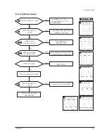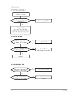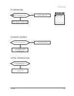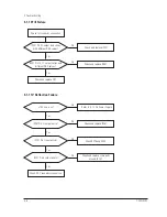
4-1-1 Before Making Adjustments
4-1-1 (a) ORIENTATION
When servicing, always face the monitor to the
east.
4-1-1 (b) MAGNETIC FIELDS
Whenever possible, use magnetic field isolation
equipment such as a Helmholtz field to surround
the monitor. If a Helmholtz field is not available,
frequently degauss the unit under test.
Caution:
Other electrical equipment may cause
external magnetic fields which may
interfere with monitor performance.
Use an external degaussing coil to limit magnetic
build up on the monitor. If an external degaussing
coil is not available, use the internal degaussing
circuit. However, do not use the internal
degaussing circuit more than once per 30 minutes.
4-1-1 (c) WARM-UP TIME
The monitor must be on for 30 minutes before
starting alignment. Warm-up time is especially
critical in color temperature and white balance
adjustments.
4-1-1 (d) SIGNAL
Analog, 0.7 Vp-p positive at 75 ohm, internal
termination
Sync: Separate/Composite
(TTL level negative/positive)
Sync-on-Green:
Composite sync 0.3 Vp-p negative
(Video 0.7 Vp-p positive)
4-1-1 (e) SCANNING FREQUENCY
Horizontal: 30 kHz to
96
kHz (Automatic)
Vertical:
50 Hz to 160 Hz (Automatic)
Unless otherwise specified, adjust at the
1024 x 768 mode (H: 68 kHz, V: 85 Hz) signals.
Refer to Table 2-1 on pages 2-2 and 2-3.
4-1-1 (f) HIGH VOLTAGE ADJUSTMENT
Signal:
1024 x 768 mode (68 kHz/85 Hz)
Display image: Full white
Contrast:
Maximum
Brightness:
Maximum
Limit:
27.3 kV ± 0.5 kV
(17Ó: 26 kV ± 0.5 kV)
Measure the hight voltage level at the anode cap.
High voltage should be within the limit as above.
If the high voltage needs adjustment
, use the VR501.
4-1-1 (g) G2 (SCREEN) VOLTAGE ADJUSTMENT
Signal:
1024 x 768 mode (68 kHz/85 Hz)
Display image: Full white
Contrast:
Maximum
Brightness:
Maximum
Adjust the Screen VR of the FBT so that the G2
(Screen) Voltage for Toshiba it is 540 V ± 10 V.
4-1-1 (h) CENTER RASTER
Adjust VR401 so that the back raster comes to the
center when you apply a signal of 91 kHz/85 Hz.
720C/920C
4-1
4 Alignment and Adjustments
This section of the service manual explains how to make permanent adjustments to the monitor. Direction
is given for adjustment using the monitor Interface Board Ver. 2.0 and software (Softjig).
4-1 Adjustment Conditions
Caution:
Changes made without the Softjig are saved only to the user mode settings. As such, the
settings are not permanently stored and may be inadvertently deleted by the user.
720C
SDD TOSHIBA
G2
525V
635V
920C
G2
560V
530V
MEC
SDD
Summary of Contents for 720C
Page 33: ...720C 920C 6 1 6 1 720C Exploded View and Parts List ...
Page 34: ...720C 920C 6 2 6 2 920C Exploded View and Parts Lists ...
Page 80: ...R299 720C 920C 10 2 10 2 MICOM Parts Schematic Diagram ...
Page 81: ...720C 920C 10 3 10 3 Horizontal Vertical Processor Parts Schematic Diagram R265 C272 R262 ...
Page 83: ...R561 R562 R501 C530 L521 R523 R526 720C 920C 10 5 10 5 High Voltage Parts Schematic Diagram ...
Page 84: ...720C 10 6 1 10 6 1 720C Video Parts Schematic Diagram ...


