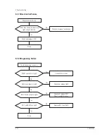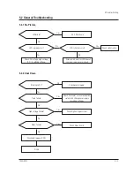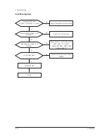
5 Troubleshooting
720C/920C
5-3
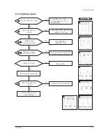
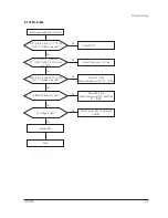
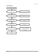
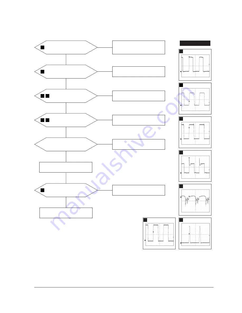
5-1-3 H_Deflection Failure
IC402 Pin 6 waveform is right?
Q403 source waveform
is right?
Check D407, D408, Q403, R436
and R438, +210 V line.
Yes
Yes
No
1. Check R401, +12 V line.
2. Check IC402 Pins 6~5, 7~6.
3. Replace IC402.
No
Q404 gate, drain
waveforms are right?
Check Q404, R415.
Check +25 V line.
Yes
No
Q405 base, collector
waveforms are right?
Check and replace D410 and Q405.
Check DY connector connection.
Yes
No
IC261 Pin 4 is high?
Replace IC261.
Check some parts around
Q261 and Q262.
Yes
No
IC261 Pin 26 waveform
is right?
Check some parts around IC261.
Yes
No
WAVEFORMS
2
3
4
5
6
8
7
3
230 V (Q405, Source)
CH1 P-P = 230 V
CH1 RMS = 150.1 V
8
12.08 V (IC261, #26)
CH1 P-P = 12.08 V
CH1 RMS = 7.396 V
2
10.96 V (IC402, #6)
CH1 P-P = 10.96 V
CH1 RMS = 6.180 V
5
54 V (Q404, Drain)
CH1 P-P = 54 V
CH1 RMS = 22.44 V
4
11.6 V (Q404, Gate)
CH1 P-P = 11.6 V
CH1 RMS = 6.944 V
6
18.6 V (Q405, Base)
CH1 P-P = 55.2 V
CH1 RMS = 9.52 V
7
1.216 kV (Q405, Collector)
CH1 P-P = 1.216 kV CH1 RMS = 316 V
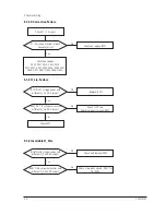
Check some parts around Q263.
Summary of Contents for 720C
Page 33: ...720C 920C 6 1 6 1 720C Exploded View and Parts List ...
Page 34: ...720C 920C 6 2 6 2 920C Exploded View and Parts Lists ...
Page 80: ...R299 720C 920C 10 2 10 2 MICOM Parts Schematic Diagram ...
Page 81: ...720C 920C 10 3 10 3 Horizontal Vertical Processor Parts Schematic Diagram R265 C272 R262 ...
Page 83: ...R561 R562 R501 C530 L521 R523 R526 720C 920C 10 5 10 5 High Voltage Parts Schematic Diagram ...
Page 84: ...720C 10 6 1 10 6 1 720C Video Parts Schematic Diagram ...


