


5 Troubleshooting
720C/920C
5-9
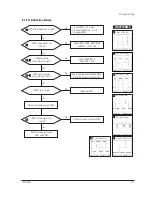
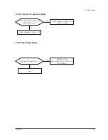
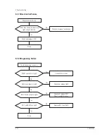
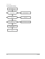
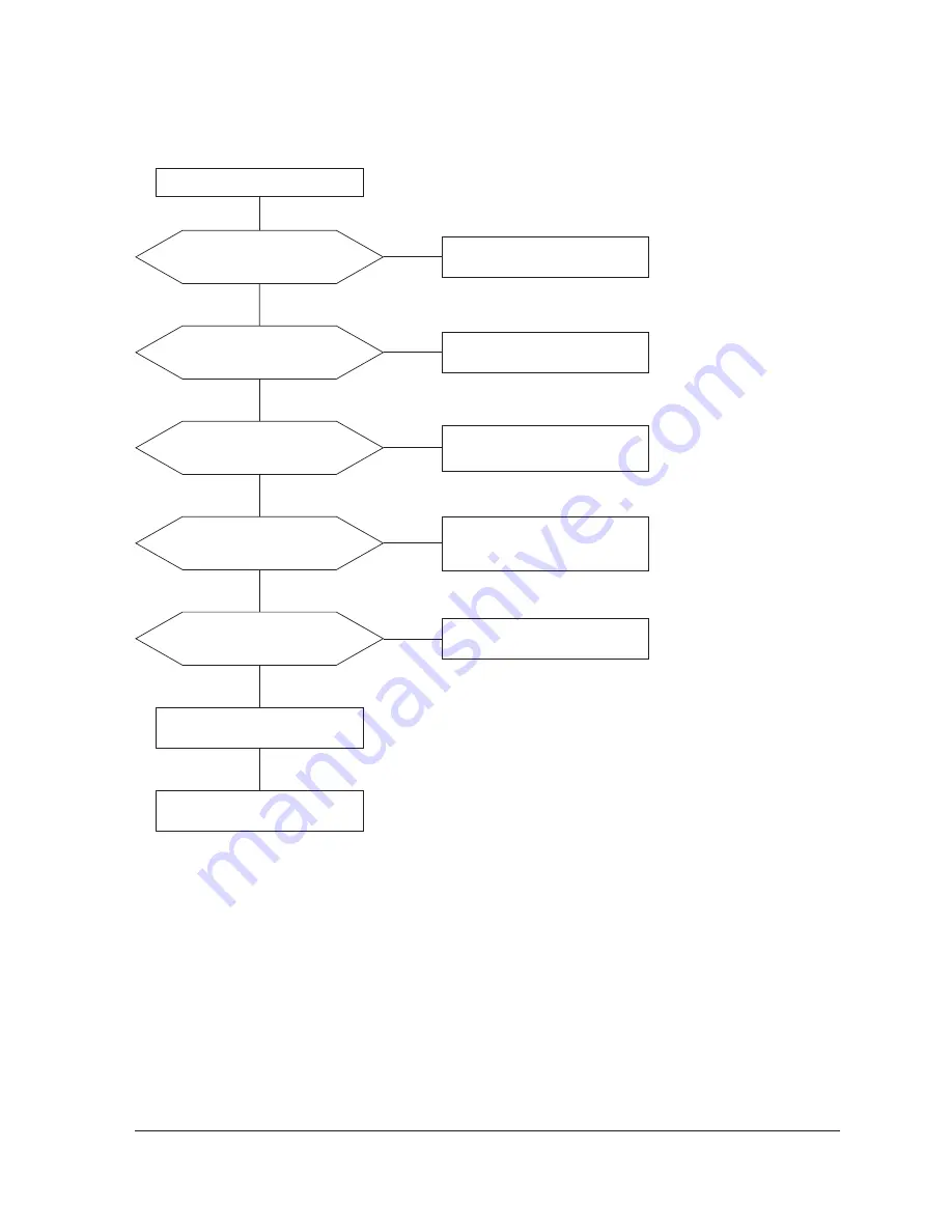
5-1-16 No Video
IC101 Pins 2, 6 and 11 (17”: IC104,
Pin 5, 8, 10) inputs are right?
IC101 Pins 29, 32 and 35
(17”: IC104, Pin 25, 28, 30) outputs
are right?
Check I
2
C bus and +12 V line.
Yes
Yes
No
Check CN101
No
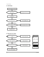
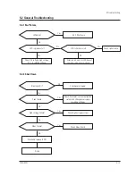
IC102 Pins 4, 6 and 14 (17”: IC105,
Pin 1, 3, 5) outputs are right?
Check +12 V line.
Check and replace IC102 (17”: IC105).
Yes
No
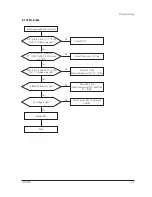
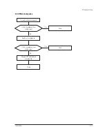
Cathode DC levels are right?
Check +80 V line.
Check and replace IC101 and IC104
(17”: IC104).
Yes
No
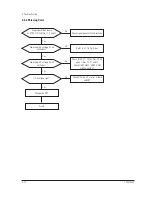
G2 voltage is right?
Check G2 wire, CRT Socket board,
and FBT.
Change CRT.
Yes
Done.
No
Check signal cable and connection.
Summary of Contents for 720C
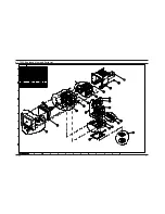
Page 33: ...720C 920C 6 1 6 1 720C Exploded View and Parts List ...
Page 34: ...720C 920C 6 2 6 2 920C Exploded View and Parts Lists ...
Page 80: ...R299 720C 920C 10 2 10 2 MICOM Parts Schematic Diagram ...
Page 81: ...720C 920C 10 3 10 3 Horizontal Vertical Processor Parts Schematic Diagram R265 C272 R262 ...
Page 83: ...R561 R562 R501 C530 L521 R523 R526 720C 920C 10 5 10 5 High Voltage Parts Schematic Diagram ...
Page 84: ...720C 10 6 1 10 6 1 720C Video Parts Schematic Diagram ...