


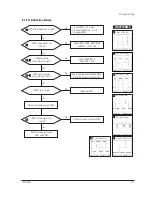

3-1-1 Before making Disassembly
1. Disconnect power cor
d from the monitor.
2. With a pad beneath it, stand the monitor on its
front with the screen facing downward and
the base close to you.
3. Make sure nothing will damage the screen.
3-1-2 Cabinet Disassembly
1
. Remove the 4 scre
ws
on the Rear Cover and
pull it
up
ward to remove it.
3-1-3 Removing the Stand
Pull the tab outward on the Chassis Bottom
and pull the Tilt and Swivel Base up to
remove it.
3-1-4 Removing the Top Shield
Remove the
4
screws on the Top Shield Cover
and remove the Shield.
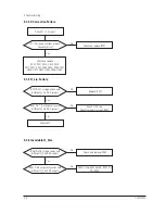
3-1-5 Removing the Bottom Shield
1. Remove the 1 screw on the Bottom Shield
Cover.
2. Lift off the Bottom Shield.
3-1-6 Removing the Video PCB Assembly
1. Remove the Video PCB from the CRT.
2. Disconnect CN102, CN10
1
, CN12 and CN13
on the Video PCB Assembly and Video PCB
AssÕy from the CRT Neck.
720C/920C
3-1
3 Disassembly and Reassembly
This section of the service manual describes the disassembly and reassembly procedures for the
Nokia 9
20C/
7
20C
(19" ~ 17")
monitors.
WARNING: This monitor contains electrostatically sensitive devices. Use caution when handling
these components.
3-1 Disassembly
Cautions:
1. Disconnect the monitor from the power source before disassembly.
2. Follow these directions carefully; never use metal instruments to pry apart the cabinet.
Summary of Contents for 720C
Page 33: ...720C 920C 6 1 6 1 720C Exploded View and Parts List ...
Page 34: ...720C 920C 6 2 6 2 920C Exploded View and Parts Lists ...
Page 80: ...R299 720C 920C 10 2 10 2 MICOM Parts Schematic Diagram ...
Page 81: ...720C 920C 10 3 10 3 Horizontal Vertical Processor Parts Schematic Diagram R265 C272 R262 ...
Page 83: ...R561 R562 R501 C530 L521 R523 R526 720C 920C 10 5 10 5 High Voltage Parts Schematic Diagram ...
Page 84: ...720C 10 6 1 10 6 1 720C Video Parts Schematic Diagram ...