PANEL5000
‐
A121
User
Manual
20
than
the
overall
size
of
the
metal
frame
that
surrounds
the
flat
panel
monitor
but
just
large
enough
for
the
rear
panel
of
the
flat
panel
monitor
to
fit
through.
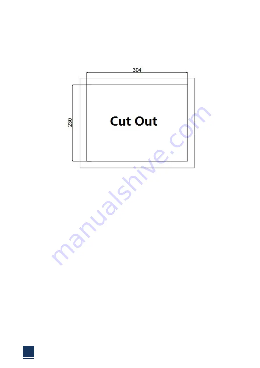
Recommended
cutout
size
as
shown
below:
Figure
2
‐
10:
PANEL5000
‐
A121
cut
out.
Step
3:
Slide
the
flat
panel
monitor,
through
the
hole
until
the
frame
is
flush
against
the
panel.
Step
4:
Insert
the
panel
mounting
clamps
into
the
pre
‐
formed
holes
along
the
edges
of
the
chassis,
on
the
two
side
of
the
frame.
Step
5:
Tighten
the
screws
that
pass
through
the
panel
mounting
clamps
until
the
caps
at
the
front
of
all
the
screws
are
firmly
secured
to
the
panel.
Summary of Contents for PANEL5000-A121
Page 1: ...PANEL5000 A121 User Manual 1 User Manual Ver1 0 PANEL5000 A121 Industrial Touch Screen Monitor...
Page 7: ...PANEL5000 A121 User Manual 7 Chapter 1 OVERVIEW...
Page 12: ...PANEL5000 A121 User Manual 12 1 5 Dimensions Figure 1 5 PANEL5000 A121 dimensions...
Page 13: ...PANEL5000 A121 User Manual 13 Chapter 2 INSTALLATIONS...
Page 29: ...PANEL5000 A121 User Manual 29 Figure 2 18 Press NEXT to continue Figure 2 19...
Page 30: ...PANEL5000 A121 User Manual 30 Press NEXT to continue Figure 2 20 Press INSTALL to continue...
Page 33: ...PANEL5000 A121 User Manual 33 Figure 2 36 Figure 2 37...
Page 35: ...PANEL5000 A121 User Manual 35 Chapter 3 System Maintenance...
Page 37: ...PANEL5000 A121 User Manual 37 A Safety Precautions...
Page 41: ...PANEL5000 A121 User Manual 41 B Hazardous Materials Disclosure...
Page 44: ...PANEL5000 A121 User Manual 44 Chapter 5 Appendix A...


