54
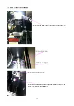
5.2 REPLACING THE BRAKE
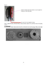
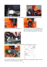
Remove 3 screws, remove the connector, then you
can remove the brake and replace it.
5.3 BRAKE CLEARANCE ADJUSTMENT
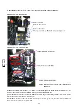
Brake coil must always be connected to the power (+24v), when energized the brake will dis engage. If
the brake system loose power, while unit is use, the unit may lose speed, and motor may reduce
excessive heat
Step 1: Measure the resistance by multimeter
(
200
Ω)
, and The Winding resistance: 25
Ω
normal (+1,-1
Ω
)
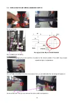
Step 2:
Loosen the three bolts that hold the brake
Summary of Contents for LPT22
Page 15: ...14 3 ELECTRICAL SYSTEM 3 1 ELECTRICAL DIAGRAM WIRING DIAGRAM ...
Page 16: ...15 CONNECTION DIAGRAM ...
Page 30: ...29 3 7 CURTIS CONTROLLER ...
Page 63: ...62 8 2 TROUBLE SHOOT ...
Page 64: ...63 ...
Page 65: ...64 ...

