


39
holding relay (J), Pin 3 must be electrically closer to b than Pin 4
Pin 4
= Relay. Pin 4 also connects in series with the circuit to be switched at empty.
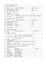
HOUR METER CONTROL LINES & IMPEDANCE SPECIFICATIONS
Min. Impedance
Low Voltage (max.) Hight Voltage (min.)
HRM+ HRM-
5.0VDC 15.0VDC 80k
Ω
20
k
Ω
HOUR METER CONTROL LOGIC
Pin 1 (HRM-)
Pin 6 (HRM+)
Hour Meter Status
High Low Off
High Open Off
Open Low Off
Open Open Off
Low High On
Low Low On
Low Open On
High High On
Open High On
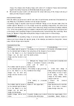
DISCHARGE ADJUSTMENTS
The followed table lists the voltages per cell under load that correspond to an empty indication on the
gauge (lockout point).
Setting K L M N O P Q R S T U
Volt/Cell
at Empty
1.57 1.63 1.68
1.73*
1.78
1.82
1.84
1.86
1.89 1.91 1.93
NOTE: “*” – factory setting
RESET TYPE/LEVEL (AFTER OR DURING RECHARGE)
CTR = Charge Tracking Reset: If the gage is connected to the battery during recharge, the gage will
track the battery charge level.
OCR = Open Circuit Reset: If the gage is disconnected from the battery during recharge, the gage will
retain the last indication. It will advance to full when reconnected only if the battery voltage is above the
OCR level. For standard (“B”) reset, OCR = 2.09 VPC (VPC = volts per cell.)
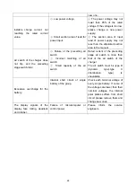
TROUBLESHOOTING
Problem Possible
Causes
No display
Terminals not connected or improper voltage
Stays at FULL
Instrument voltage does not match battery voltage, B+ connected
to the wrong terminal
Will not reset
Instrument voltage does not match battery voltage, or battery not
fully charged
Resets w/o charging battery Not connected directly to battery terminals
EMPTY too soon
B+ connected to wrong terminal, or instrument voltage does not
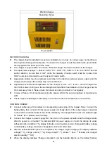
Summary of Contents for LPT22
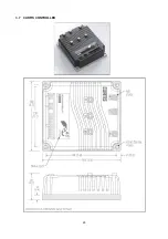
Page 15: ...14 3 ELECTRICAL SYSTEM 3 1 ELECTRICAL DIAGRAM WIRING DIAGRAM ...
Page 16: ...15 CONNECTION DIAGRAM ...
Page 30: ...29 3 7 CURTIS CONTROLLER ...
Page 63: ...62 8 2 TROUBLE SHOOT ...
Page 64: ...63 ...
Page 65: ...64 ...


