


47
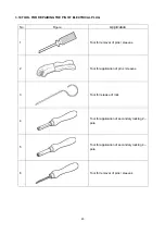
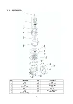
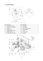
1. Elastic
washer
7. Mounting
bracket 13.
Combination
washer
2.
Shaft
8.
Joint seat
14.
Pump motor
3.
Bush
9.
O-ring
15.
Mounting plate for valve
4.
Holding bracket
10. Rubber oil pipe
16.
Oil tank
5 cylinder
11. bolt
17.
Bush
6. Bolt
12. Combination
washer
18.
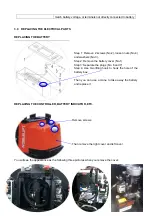
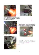
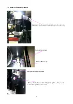
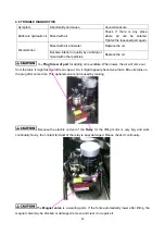
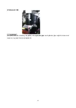
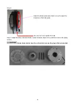
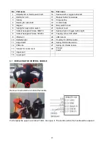
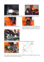
4.3 REPLACING THE POWER UNIT
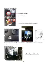
Remove the relay cable.
Remove the pipe.
Remove 2 screws.
Then you can remove the power unit and replace it.
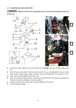
Collapse the forks to the loweredd position. Then drain the hydraulic oil from the
power unit.
Summary of Contents for LPT22
Page 15: ...14 3 ELECTRICAL SYSTEM 3 1 ELECTRICAL DIAGRAM WIRING DIAGRAM ...
Page 16: ...15 CONNECTION DIAGRAM ...
Page 30: ...29 3 7 CURTIS CONTROLLER ...
Page 63: ...62 8 2 TROUBLE SHOOT ...
Page 64: ...63 ...
Page 65: ...64 ...


