background image


89 

6. Safety problem in battery usage   
  (1) No smoking 

·Batteries produce hydrogen gas. Short circuit will produce sparks when lit cigarette 

near the battery, it will cause an explosion and fire. 


(2) Avoid electrical attack 

·

Battery with high voltage, when the installation and maintenance, do not touch the 

battery conductor, which can cause serious burns. 

        (3) Correct link   

·When the battery charging, the positive and negative can not be reversed, otherwise 

it will cause heat, fire, smoke or explosion. 

  (4) Do not put metal objects on the battery 

·

Do  not  let  positive  and  negative  contacts  cause  a  short  circuit  by  bolts  or  tools, 

which will result in injuries and explosions. 

(5) Against excessive discharge 

·

Do not use forklift until it can not move, otherwise the battery life will be shortened. 

The  batteries  need  charging  up  when  the  battery  capacity  warning  light  flashes 
continuously. 

(6) Keep clean 

·Keep the battery surface clean. 

·Do not use dry cloth, chemical fiber cloth to clean the battery surface. Do not use 

polyethylene film covered battery. 

·Static electricity can cause an explosion. 
·Clean the top of the battery not covered with a moist cloth. 

(7) Wear protective clothing 

·When  maintain  the  batteries,  you  should  wear  goggles,  rubber  gloves  and  rubber 

boots. 


Summary of Contents for FE4P40N

Page 1: ...nderstanding the operating instructions as well as the waring decals on the truck Keep for future reference FE4P40N FE4P45N FE4P50N Operation and maintenance manual FEXP type battery counterbalanced f...

Page 2: ...e system 16 2 1 Summarize 16 2 2 Brake paddle 16 2 3 Brake base pump 17 2 4 Brake staff 18 2 5 Parking brake operating device 20 2 6 Gist of dismantlement and regulating for brake staff 20 2 7 Adjusti...

Page 3: ...tinglocationforpartsdisassembled 61 Chapter Three Operation use and safety for forklift 63 Driving and operation 63 1 Usage of new vehicle 63 2 Connection between load and stability 63 3 Load center a...

Page 4: ...ck before operation 92 1 Checkingpointandcheckingcontent 92 2 Checking procedure 92 Check after operation 94 Truck cleaning 94 1 Truck surface cleaning 97 2 Chains cleaning 97 3 Electric system cleani...

Page 5: ...e operation if not do so it should lead to injury on human or damage on equipments and fire 2 Regulations that you need to pay attention and have to comply with before operation if not do so it should...

Page 6: ...er 9 Loosen parking brake 10 Try to lift and lower the mast tilt forward and backward the mast turn and brake the truck 11 Be sure that the polluting level of hydraulic oil is less than 12grade 4 Oper...

Page 7: ...ght the brake apparatus and plug the wheels with wedge if the parking time is long 21 The protection valves on multiway valve and on steering device are already regulated so the users shouldn t regula...

Page 8: ...7 Chapter two The main performance parameters of forklift truck The truck s outline dimension and performance parameters 1 The truck s outline dimension see figure 1 1 Figure 1 1 outline...

Page 9: ...ft height h2 mm 150 150 150 Lift height h3 mm 3000 3000 3000 Extended mast height h4 mm 4117 4117 4117 Overhead load guard height h6 mm 2265 2265 2265 Seat height h7 mm 1200 1200 1200 Traction pin hei...

Page 10: ...h2 mm 150 150 150 Lift height h3 mm 3000 3000 3000 Extended mast height h4 mm 4117 4117 4117 Overhead load guard height h6 mm 2265 2265 2265 Seat height h7 mm 1200 1200 1200 Traction pin height h10 m...

Page 11: ...l direction changes too 1 1 2 Reducer casing and differential mechanism Reducer of which the two pairs of column screw gear make the rotational speed decline of the output axis of travel motor and mak...

Page 12: ...ial is left right subdivision in construction and there are two half axle gears and four planet gears in it see figure 2 2 1 bearing 2 bolt 3 Right differential housing 4 cushion ring 5 half axle gear...

Page 13: ...el hub see figure 2 3 1 Half shaft bolt 2 left half axle 3 gland 5 lockwasher 80 6 Bridge housing assembly 7 breather plug 4 nut M80X2 8 stop up 9 Right half axis 10 Right brake assembly 11 hub nut 12...

Page 14: ...nut and cock up lock plate to stop nut 5 Tyre assembly figure 2 6 Fix gas pole and nut cap upon tyre and assemble wheel rib pay attention to the following items Attention a Gas pole lies in the gap of...

Page 15: ...ke a lot the fastening bolts loosen Tighten Too high of oil temperature gear oil deteriorates replacing Un usual Oil level Supplying or reducing Clamping stagnation of moving parts adjustment oil leak...

Page 16: ...gear of decelerator is connected directly with the travel motor so the driving speed of forklift increases with the increase of motor speed and the driving direction can be changed by changing the dir...

Page 17: ...ing ring 62 Locking pin 63 Spring 64 Stud 65 Spring Figure 2 7 Decelerator 1 2 2 Care and maintenance 1 Before conducting running in test of the gear box users shall fill in gear oil gear oil shall be...

Page 18: ...flow back to oilcan through oil return hole until the base leather cup plugs the oil return hole After the base leather cup push over the oil return hole the brake fluid of the front cavity of base pu...

Page 19: ...of the brake shoe which holds back the parking brake parts through rebound spring and Pressure spring contacts with fixing pin and another end of it contacts with regulator In addition there are brake...

Page 20: ...consists of pulling rod and pushing rod is assembled in wheel brake stuff The pulling rod of which the action is transported to the side of secondary brake shoe is installed on the side of leading br...

Page 21: ...er clockwisely the brake force increases Turning the adjuster counter clockwisely the brake force decreases Pulling force 196N 294N figure 2 14 gap self regulating device figure 2 15 parking brake han...

Page 22: ...brake pump Disassemble scraper seal Press one terminal piston to push out another terminal one then push out the rest one with finger See figure 2 22 figure 2 22 2 6 2 Brake device inspection Inspect...

Page 23: ...spring on hand brake handspike hen fix handspike on brake hoof See figure 2 27 figure 2 25 figure 2 26 figure 2 27 8 Fix guide of brake shoe on brace pin then fix rebound spring of brake hoof Install...

Page 24: ...en pulling adjusting bar a Ensure adjusting bar ejector pin ejector pin spring and spring are all fixed b Check rebound spring of ejector pin and spring of adjustor check adjuster gear for running sta...

Page 25: ...witch to make clearance into A 1mm d To be sure when step pedal down the light of brake shall be open e Tighten the nut figure 2 32 braking light button 2 8 Malfunction and cause See List 2 3 List 2 3...

Page 26: ...system leakage Repair or replace 2 Clearance of brake hoof is not ok Regulate adjustor 3 Air in brake system Deflate air 4 Brake pedal adjusting is not ok Adjusting again 2 9 Maintenance Before runnin...

Page 27: ...lexion Now you can place retainer washer and tighten lock nut 3 Steering system 3 1 Summary Steering system see figure 2 33 consists mainly of steering wheel steering shaft steering device steering oi...

Page 28: ...the parts as steering axle body steering cylinder connecting rod steering knob steering wheel and so on Steering trapezium is crank block in construction that the cylinder piston rod by connecting rod...

Page 29: ...pring washer 14 bolt 15 close over 16 bearing 17 adjusting shim 18 bearing 19 Right knuckle assembly 20 nut 21 spring washer 22 screw 23 Lip seal ring 24 bearing 25 hub 26 bearing 27 nut 28 lockwasher...

Page 30: ...shim 4 bearing 5 knuckle 6 gasket 7 gasket ring 8 king pin figure 2 36 2 Steering cylinder Steering cylinder designed as a double acting piston in pattern that is the piston rod connects on each end t...

Page 31: ...htening nut again at this time the torque is 9 8N m 1kgm 4 Tap wheel hub gently by wood hammer and rotate wheel hub 3 4 circle to ensure there is no loose of wheel hub 5 Tighten castle nut and make sl...

Page 32: ...re air in oil circuit exhaust air failure of steering reset Rivet spring slice broken or elasticity is not enough replace spring slice too big inside leakage of steering cylinder check piston seal For...

Page 33: ...e pump Figure 4 7 Traction controller double wheel drive Pump controller Double pump Figure 4 8 Forklift traction AC frequency conversion motor steering AC frequency conversion motor controller dashbo...

Page 34: ...33 4 1 1 Electrical principle chate Figure4 8 1 Single wheel drive and double pump...

Page 35: ...34 Figure4 8 1 Double wheel drive and double pump...

Page 36: ...expected unsafe operations from occurring There is a time delay of several seconds at the input end of the seat switch To allow the seat switch to be temporarily disconnected in the event of a jolt 7...

Page 37: ...indication The arrow represents the direction of the steering wheel Working mode indication Display the current mode of work S tortoise speed P E 3 working mode Speed display Display current vehicle...

Page 38: ...Switch to mode at main interface S P E Number 3 Switching between the main interface and the secondary interface Number 4 Speed unit KM h and MPH unit switching 4 1 5 Fault analysis ACS Controller fau...

Page 39: ...16 45 Traction controller encoder fault 1 Traction controller encoder fault 2 Traction motor speed sensor connection wire is open 17 81 Traction controller temperature is low Traction controller tempe...

Page 40: ...ehicle overload or Mechanical clamping 2 Traction motor speed sensor fault 34 105 Traction controller precharge failed Replace the pre charge resistance 35 110 DC bus voltage of traction controller is...

Page 41: ...s high cut back 54 143 Pump motor temperature is high cut back Pump motor temperature is high alarm 55 144 Pump controller current calibration error Reset key 56 145 Pump controller precharge failed R...

Page 42: ...R VOLTAGE HIGH RESET KEY 77 49 DC MOTOR OPERATING CURRENT IS ZERO HPG CONRTOLLER SENSOR FAULT 78 53 HPG CONRTOLLER OVER CURRENT HPG CONRTOLLER OVER CURRENT 79 62 HPG CONTROLLER TEMPERATURE HIGH HPG CO...

Page 43: ...42 89 246 HPG CONTROLLER WAITING FOR MAIN CONTACTOR TURN OFF THE PUMP CONCTACTOR PARAMETER 90 161 DISPLAY CAN FAULT CHECK DISPLAY AND CONTROLLER CAN CONNECTION...

Page 44: ...n please read operation instruction manual carefully keep the manual with you after reading so as to get convenience of it at any time 5 2 Battery use requirements The lifespan of battery is between 2...

Page 45: ...y your eye parallel with density and let floater locate central position and not to touch with pipe wall to avoid influencing reading accuracy If temperature is lower than 25 or upper than 25 measure...

Page 46: ...ng course In normal charging Open cover of oil inlet check if the electrolyte level is in normal height otherwise regulate it to the normal height by distill water Connect charger to battery correctly...

Page 47: ...cylinder 12 tilt cylinder figure2 48 Hydraulic system diagram 6 2 Oil pump Oil pump is gear pump 6 3 Multiway valve The multiway valve is two piece four body in pattern the high pressure oil from wor...

Page 48: ...valve can return on neutral 2 Motion of safety flooding valve There is a flooding valve between pump HP and low pressure chunnel LP Pressure liquid from lifting valve c play on piston A and piston B...

Page 49: ...into tilting cylinder through joint B liquid returned from cylinder play on piston through oil pore A Liquid return to tank through pore A or B of valve core See figure 2 53 b When pump is not working...

Page 50: ...piston rod piston cylinder head etc Two lift cylinders located on rear of outer mast its bottom fitted on seat of lift cylinder of outer mast by pins and bolts the top of cylinder i e top of piston ro...

Page 51: ...hain Stop valve motion principle There is a stop valve on bottom of cylinder figure 2 57 if high pressure pipe burst suddenly this valve can prevent load lowering sharply Liquid from lift cylinder flo...

Page 52: ...here are shaft sleeve Yx seal retainer ring and dust ring in guide sleeve this shaft sleeve support piston rod seal ring retainer ring and dust ring to prevent leakage and dust it is screwed onto cyli...

Page 53: ...in rear right of framework There are net filter in oil tank and breather on oil tank cover see figure 2 60 1 dipstick 2 bolt 3 washer 4 spring washer 5 Sealing gasket 6 Combined washer 7 drain plug 8...

Page 54: ...ump 2 hydraulic steering gear 3 tilt cylinder 4 multiple unit valve 5 oil pump 6 oil tank 7 steering cylinder figure2 61 hydraulic pipeline 6 8 Maintenance and adjustment Working cylinder maintenance...

Page 55: ...ace pump body Figure 2 62 figure 2 63 b Lining slice inspection Check interface of lining slice if surface damage or thickness of lining slice is less than normal value 4 94mm please replace it Figure...

Page 56: ...g at forklift also to be available as follows if pump abrasion badly or locking attributed to hydraulic liquid and being disassembled you shall renew hydraulic liquid and filter before commissioning a...

Page 57: ...Replace spring Valve base bad Adjust or replace flooding valve Leak inside Valve base bad Amend valve base surface Enactment pressure too high Valve get stuck Break up cleaning 2 Hydraulic pump fault...

Page 58: ...rive axle by brace Middle of outer mast connect with frame through tilting cylinder and it can tilt forward and backward actuated by tilting cylinder 1 circlip for shaft 2 roller 3 bolt 4 spring washe...

Page 59: ...erse load borne side roller 1 Load backrest 2 washer16 3 spring washer16 4 bolt 5 Longitudinal roller 6 circlip for shaft 7 adjusting washer 8 adjusting washer 9 Side roller 10 washer12 11 spring wash...

Page 60: ...gulate shim to fit head of piston into upper beam of inner mast 2 Lift mast slowly to its maximum journey to check both of cylinder to move simultaneously 3 Put adjusting shim into between head of pis...

Page 61: ...To be sure new roller is normal and fit it on its position and lock it by clip ring Figure 2 73 Figure 2 74 7 5 4 Replace mast roller see figure 2 74 1 Dismantle the fork carriage from inner mast with...

Page 62: ...other metal item from you to prevent suddenness short circuit 4 During disassembling please use normal tools use special appointed tools when requested 5 Choose optimum elevating equipment to hoist pa...

Page 63: ...es 5 Hoisting directions of travel motor see figure 2 79 6 Hoisting directions for working motor see figure 2 80 Type outline dimension length width height mm Weight kg FE4D50 1048 913 866 1840 FE4D45...

Page 64: ...rgo cg Said figure of load curve show you relation of 2t forklift load centre and permitted load figure of load curve is adhibited on vehicle if figure damaged to renew it in time If forklift is equip...

Page 65: ...ignition key and keep it at ON position Even after ignition key is turned to ON position 1 second is needed between brake circuit starting to work and starting to move If gear shift lever is in forwar...

Page 66: ...g simultaneously Inching operation a Traveling first let fork prong be close to goods about 3 5m distance b Step brake pedal down perfectly standstill c Step accelerator down to be in optimum speed d...

Page 67: ...truction of operating manual a Keep liquid on normal level Keep liquid level on normal situation to prevent battery from being over hot or being burn out If electrolyte is not enough the life span of...

Page 68: ...of battery to avoid cover fall down to injure human or bodywork c When hoisting battery out forklift be careful for touching steering wheel or other forklift parts d After finish installation of batt...

Page 69: ...of goods 11 Transport the goods to destination 12 Deposit 1 Before diposit Before forklift deposits clean it thoroughly check up as following a If necessary clean grease and oil of bodywork by cloth a...

Page 70: ...bared parts c Cleaning impurity and water of hydraulic tank d Install full charged battery on forklift andconnect it e Check carefully before startup Using instruction of operating devices 1 Componen...

Page 71: ...ed by direction switch steering switch and big and small light switch 1 direction switch 2 steering switch 3 big and small light switch Direction switch controls travelling direction and delivers sign...

Page 72: ...of multiway valve Both hydraulic steering system and steering wheel tilting device are standard equipment of forklift According to driver seat to adjust steering wheel to optimum angle Lock steering...

Page 73: ...andle step down the parking paddle 5 Brake paddle and accelerating paddle Do not step accelerator pedal suddenly to prevent the vehicle from starting or accelerating suddenly Ensure your foot remove f...

Page 74: ...t operating handle Lock will be released after pull the handle up you can move seat to and fro gently To be sure seat locked after adjusting Seat adjusting range To and fro is 120mm When traveling on...

Page 75: ...roof grard when get on or get off please use foot pedal and armrest to ensure your safety 7 Lamps There are head light and front light assembled on the head of vehicle direction indicator lamp parking...

Page 76: ...hould be adjusted appropriately in ramps or rough pavement to be especially careful when driving Driving on a ramp or rough roads will speed up the forklift tire wear and increased noise 2 Work enviro...

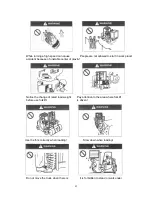
Page 77: ...hange parts on forklift arbitrary Read the instruction manual carefully before without permission driving Turn off the engine before maintenance Understand traffic regulations Before use please check...

Page 78: ...s cap clean Do not drive an unsafe forklift Drivers should have a healthy body Be sure your truck is safe Work in specified area Do not drive a damaged truck Hold tightly when get on the truck Start f...

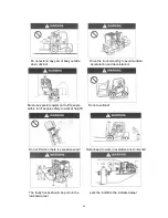
Page 79: ...ition Appropriate fasten seat belts Always pay attention to the height of work place Turn on lights in dark area Do not put arm and body outside of the overhead guard during work Avoid driving on soft...

Page 80: ...y front fork when loading Check fork pin position Note the security of the work region Do not run on smooth or slippery ground Note the horizontal driving stability of the truck when it is un load Be...

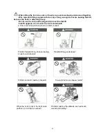
Page 81: ...lowly handling small objects Do not chase each other through the traffic Not allowed to stand on the goods Not allowed to gaze around while driving Do not use the forklift to do stunt when goods is so...

Page 82: ...lifting height When no load travel backward in upgrade Note using brake when start truck on and travel forward in downgrade the slopes Not turn when driving on a slope People or things moving on road...

Page 83: ...cident because of unstable center of gravity Notice the change of rated load weight Pay attention to the area where forklift before use forklift is driven Use the fork correctly when loading Slow down...

Page 84: ...r Please bind the goods which is difficult than the goods rest to fix before load Do not carry the goods from forklift by Do not let people to carry the goods have manpower been damaged Do not misuse...

Page 85: ...n and deceleration Must use special equipment to lift people Do not overload safely to lift people safely to work at height Do not lift when there is excessive wind Not allowed to work in explosive en...

Page 86: ...key 3 Move the truck Forbid hoisting from the top Forbid hoisting on the frame Hoisting the forklift correctly Hoisting the forklift Tie firmly steel cable on two terminal holes of outer mast beam and...

Page 87: ...ad guard to hoist the forklift Forklift upgrade do not enter the truck underneath 4 How to avoid overturning how to protect yourself Prohibit forward tilt to enhance loading Prohibit lifting goods tip...

Page 88: ...is more safe to stay under the protection of seat belt than jump down the truck If the forklift began to tip over 1 Tap foot and clench the steering wheel tightly 2 Do not jump 3 The body bend to the...

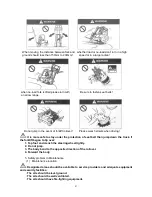
Page 89: ...e search for medical treatment immediately Do not use the door frame assembly as a ladder Strictly forbidden to put your hands feet and body between frame and door frame assembly 4 Inspect and replace...

Page 90: ...battery Do not let positive and negative contacts cause a short circuit by bolts or tools which will result in injuries and explosions 5 Against excessive discharge Do not use forklift until it can no...

Page 91: ...ediately take off clothes 10 Close battery cover tightly Cloth battery upper cover tightly to prevent electrolyte from leaking Do not add too much electrolyte electrolyte overflow will cause leakage 1...

Page 92: ...ns plate on again if they fall of 1 Battery maintenance instructions 2 Warning 3 Company identification 4 Hoisting marking 5 hydraulic fluid 6 Model 7 Squeeze marking 8 Prohibition of lifting 9 Stoppi...

Page 93: ...nto the water pipe under the soil burning etc will pollute the water soil atmosphere etc which is prohibited by law 1 Checking point and checking content No Checking points Checking contents Brake sys...

Page 94: ...distance about 2 5m 2 Check the brake oil Open the lid and check the brake oil and other conditions 3 Check parking brake handle Push forward parking brake handle and observe following status If there...

Page 95: ...rame function Check the upgrade and after dumping the normal operation is smooth 7 Check pipeline Check lift cylinder tilt cylinder and all pipeline whether oil leak 8 Check the hydraulic oil Land the...

Page 96: ...nut loosening is very dangerous if loose the wheels may fall off resulting in vehicle flip Check the availability of loose wheel nut it is very dangerous even one of them is loose so be screwed to the...

Page 97: ...guard and load backrest Check whether there are loose bolts or nuts 16 Check the integrity of vehicle identification 17 Others Check whether abnormalities other parts In addition to checking lights a...

Page 98: ...to clean trucks take safety measures to prevent short circuit Use water and soluble detergent to clean the truck Clean the oil filler and periphery of grease tap carefully If regular cleaning truck pl...

Page 99: ...200h Battery Electrolyte levels Eye survey Electrolyte specific gravity Gravi meter Quantity of electricity Terminals are loose The cable is loose Surface cleaness of the battery Battery surface has p...

Page 100: ...Six months 1200h Gearbox and Wheel Reducer Noises Check leakage Change oil Check the working condition of brake Check the moving of qear wheel Check the junction with the frame bolts loose situation C...

Page 101: ...nditions Check whether steering cylinder is leaking Check rack and pinion gear case wiring and working condition of sensor 7 Brake system Mainten ance item Maintenance item Tools Every day 8h Every we...

Page 102: ...ion is lossen Operation condition Multitande m valve Leakage Safety valve and self locking tilt valve operation condition Measuring the pressure of the safety valve Oil gauge Pipeline joint Leakage lo...

Page 103: ...een inner mast outer mast and beam is cracking or damaged or not Tilt cylinder bracket and the door frame weld whether cracking damage Inner frame outer frame weld whether cracking damage Fork frame w...

Page 104: ...lt to find through regular maintenance of injury or damage in order to further improve security the user should replace the parts given in the following table for regular If the parts appeared abnorma...

Page 105: ...rademark Capability L Remark Hydraulic oil L HM32 Max70 5 L HV32 20 Gear oil 85W 90GL 5 12 single drive 3 double drive 15 49 80W 90GL 5 25 49 Brake fluid Caltex DOT3 0 2 Industrial Vaseline 2 Battery...

Page 106: ...105 Maintenance record No Date Maintenance content Noter...

Page 107: ...6 FE4P40N FE4P45N FE4P50N NOBLELIFT INTELLIGENT EQUIPMENT CO LTD Service hotline 4008 836115 Wechat nuolijixie Postcode 313100 Email address info noblelift com Website www noblelift com Version Jan 20...

Reviews: