background image

Use and Maintenance Manual model “H14 V SHAPE”


ENGLISH

1.8 SPARE PARTS

Only use original spare parts.

Do not wait for the components to wear from use be-

fore replacing them.

This measure promotes prevention of accidents 

caused by people, animals or property in the event 

of product malfunctioning caused by faults.

You are advised to contact authorised staff to re-

place spare parts, worn parts and for extraordinary 

maintenance of the the product.

1.9 IDENTIFICATION PLATE

The plate placed on the back of the product outlines 

all the characteristic data of the appliance, includ-

ing the manufacturer's data, the serial number and 

the CE marking.

1.10 DISPOSAL OF THE PRODUCT

Demolition and disposal of the product is the exclu-

sive responsibility of the owner, who should do so in 

compliance with legislation in force in his 

country on safety matters, with respect of and safe-

guarding the environment.

At the end of its useful life, the product must not be 

disposed of as urban waste.

It  can  be  delivered  to  specific  differentiated  waste 

collection centres made available by municipal ad-

ministrations, or dealers who provide this service.

Disposal of the product as differentiated waste 

means possible negative consequences for the envi-

ronment and health are avoided, deriving from

inadequate disposal. Furthermore, it allows 

recovery of materials composing the product to 

obtain important savings in energy and 

resources.

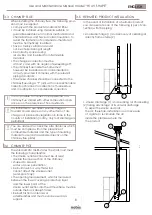
1.11 HERMETIC PRODUCT

The products manufactured with a perfectly her-

metic structure do not consume oxygen in the envi-

ronment, since they take all the air from outside the 

home (if correctly installed) and can therefore be 

positioned inside all homes with a high level of insu-

lation, such as “passive houses” or “with high energy 

efficiency”. Thanks to this technology, there is no risk 

of smoke emissions in the environment and no venti-

lation grates are necessary.

As a result, no cold air flows are created in the en

-

vironment making it less comfortable and reducing 

the overall efficiency of the system. Hermetic prod

-

ucts can also be installed in the presence of forced 

ventilation or in premises which can go into negative 

pressure compared to outside.

2

CHARACTERISTICS OF THE PELLETS

Wood pellets are fuel made of pressed sawdust, of-

ten recovered from carpentry processing waste. The 

material used cannot contain any foreign substance 

such as glue, varnish or synthetic substances.

Sawdust, after drying and cleaning of impurities, it 

is pressed using a matrix: due to the high pressure, 

the sawdust heats activating the natural binders in 

the wood; by doing so, the pellet maintains its shape 

even without adding artificial substances. The density 

of wood pellets varies based on the type of wood 

and can exceed 1.5 - 2 times that of natural wood.

The cylinders have a diameter of 6mm and a 

variable length of 10 to 40mm.

Their density is equal to approx. 650 kg/m3. Due to 

the low water content (< 10%), they have a high en-

ergy content.

The main quality certifications for pellets on the Euro

-

pean market today guarantee the fuel is within 

class A1/A2 

according to ISO 17225-2:2014 (formerly EN 14961). 

Examples of these certifications are for example EN

-

Plus, DINplus, Ö-Norm M7135, and guarantee they 

comply in particular with the following characteris-

tics:

• heating power: 4.6 ÷ 5.3 kWh/kg;

• water content: ≤ 10% of weight;

• percentage of ash: max 1.2% of weight 

   (A1 under 0.7%);

• diameter: 6±1/8±1 mm;

• length: 3÷40 mm;

• content: 100% untreated wood without 

   any additional binder substances (percentage of 

   bark max 5%);

• packaging: in sacks made from 

   eco-compatible or 

   bio-degradable.

The manufacturer recommends, for its products, use of 

class A1 and A2 certified fuel according to the stand

-

ard En ISO 17225-2:2014, or certified DIN

PLUS (more restrictive than class A1) or O-NORM M7135.

Pellets must be kept in a dry environment which is not 

excessively cold. You are also advised to keep some 

bags of pellets where the product is installed and op-

erating, to dry them of any humidity present.

Non-compliance with this aspect reduces the ther-

mal power of the fuel and means greater mainte-

nance must be done on the product.

Summary of Contents for H14 V SHAPE

Page 1: ...EN Installation use and maintenance manual H14 V SHAPE...

Page 2: ...appropriate place having carefully consulted it Improper installation maintenance not carried out correctly and improper use of the product relieve the manufacturer of any liability towards people or...

Page 3: ...8 Description of remote controls 21 8 1 Description of receiver 21 8 2 Description of handheld device keys 21 8 3 Description of handheld device display 22 8 4 Flat battery signalling 22 8 5 Concise i...

Page 4: ...ty and maintenance of safety devices do not remove or bypass this devices 1 3 IMPROPER USE The product must be intended for the use for which it was expressly designed for any other use the manu factu...

Page 5: ...on conforming installation with that specified by the manufacturer refer to the installation and use manual supplied with the appliance further damage caused by wrong intervention by the user in an at...

Page 6: ...ng it less comfortable and reducing the overall efficiency of the system Hermetic prod ucts can also be installed in the presence of forced ventilation or in premises which can go into negative pressu...

Page 7: ...ms garage etc and must have a net useful section equal or higher than 80 cm2 pellet burning stoves and thermostoves EN 14785 and 100 cm2 for boilers EN 303 5 The air intake is not necessary for instal...

Page 8: ...rm of dis charge not planned by legislation in force in the country of installation In Italy only roof discharge is permitted 3 4 CHIMNEY POT The standard UNI 10683 states the stack must meet the foll...

Page 9: ...parts such as wood etc In both cases insert adequate insulation 5 be tween the chimney flue and the attic You are advised to check and comply with the plate data of the chimney flue in particular the...

Page 10: ...ician NOBIS SRL cannot be held in any way liable in the event of non compliance with the installation and start up standards of its products 3 8 PRODUCT UNPACKING Packaging is composed of boxes in rec...

Page 11: ...ide panel from the packaging and insert the hooks placed in the lower part of the same in the slits placed on the base of the product Bring the panel to the vertical position and fasten the upper part...

Page 12: ...ll the steps to perform the hydraulic connection of the appliance to the dwelling system are illustrated The connection of the product to the hydraulic system must be carried out exclusively by specia...

Page 13: ...r civil use before installing the appliance is paramount EXPANSION VESSEL The product is equipped with an expansion vessel to compensate for the increase in water pressure inside the boiler in case of...

Page 14: ...a pavimento Riscaldamento a termosifoni Valvola a tre vie Risc Sani Accumulo ACS Bollitore Flussostato ACS Valvola miscelatrice Accumulo acqua tecnica Puffer 11 12 13 14 15 16 17 18 19 8 DIAGRAM 00 D...

Page 15: ...re vie Risc Sani Accumulo ACS Bollitore Flussostato ACS Valvola miscelatrice Accumulo acqua tecnica Puffer 11 12 13 14 15 16 17 18 19 1 2 3 4 5 6 7 2 9 11 12 12 13 14 10 8 15 16 17 18 DIAGRAM 01 DIREC...

Page 16: ...a tre vie Risc Sani Accumulo ACS Bollitore Flussostato ACS Valvola miscelatrice Accumulo acqua tecnica Puffer 11 12 13 14 15 16 17 18 19 1 2 3 4 6 7 2 9 11 12 12 13 14 10 8 18 10 19 DIAGRAM 02 TECHNIC...

Page 17: ...parete Riscaldamento a pavimento Riscaldamento a termosifoni Valvola a tre vie Risc Sani Accumulo ACS Bollitore Flussostato ACS Valvola miscelatrice Accumulo acqua tecnica Puffer 6 7 8 15 16 17 DIAGR...

Page 18: ...ANCE The maintenance operations excluding routine cleaning explained in the relevant paragraph must be carried out by authorised technical staff Remember before carrying out any maintenance operation...

Page 19: ...E TREATMENT DISEGNATORE SCALA SCALE FORMATO FORMAT STATO STATUS REVISIONE REVISION TOLLERANZE GENERALI SECONDO LA CLASSE UNI EN 22768 mK GENERAL TOLERANCES AS PER UNI EN 22768 mK NOBIS S r l N DISEGNO...

Page 20: ...ded by inserting pellets from the upper part of the product opening the door Ensure the content of the bag of pellets does not fall around the edges of the tank paying particular attention to centring...

Page 21: ...y re mote board placed at the back of it which allows basic management of the functions in the event the handheld device is faulty or not working properly 1 Serial connection use by authorised staff O...

Page 22: ...nal will confirm the change OK From STAND BY mode pressing allows to obtain an overview of the actual and active device status as shown in the following figure 8 4 FLAT BATTERIES SIGNAL If batteries a...

Page 23: ...tying ACTIVE COMFORT CLIMA RESTART FROM COMFORT CLIMA FINAL CLEANING OFF ALERT see specific paragraph FLAME OVERHEATING PELLET OVERLOAD 8 5 CONCISE ICONS DIAGRAM 1 2 4 3 MEANING H2 O STANDBY FAULT PRE...

Page 24: ...eference standard thermostat OPERATING PROCEDURE MENU USER SETTINGS SETTINGS PROBE CALIBRATION Access menu by pressing Scroll down entries to select USER SETTINGS using Access menu by pressing OK OK B...

Page 25: ...signalling causes switching off of the prod uct as well as resetting of any alarms For models with an automatic cleaner during the switch on phase the product activates a brazier cleaning phase befor...

Page 26: ...ermines the temperature gradient according to which the appliance must restart STATUS SCREEN To see the shutting down of the appliance while in COMFORT CLIMA mode screen must be displayed To see that...

Page 27: ...d so as to turn it off once the temperature in the room where the product is in stalled has been reached by means of the remote control and using only an external thermostat for the device environment...

Page 28: ...LEAN ING status before starting the function The number expressed in seconds indicates the rota tion time of the auger during the loading phase After this time is up the auger stops automatically afte...

Page 29: ...m by pressing the key and pass to edit extraction OK Edit the extraction setting keys The values vary from 5 reduction in extraction in to 5 increase in extraction in Confirm by pressing the key and e...

Page 30: ...ing system in the presence of DHW storage tank with SUMMER settings OPERATING PROCEDURE MENU USER SETTINGS SETTINGS SEASON Access menu by pressing Scroll down entries to select USER SETTINGS using Acc...

Page 31: ...ND BY screen use the key repeating the operation multiple times 12 10 ANTICONDENSATION exhaust fumes temperature This function ensures that the temperature of exhaust gases remains higher than condens...

Page 32: ...ge or by pressing button An acoustic signal will confirm the change OK The operation is the same as the one described in the basic diagram with the only difference that here the product exchanges dire...

Page 33: ...heating by means of a con tact or immersion probe not provided always to be connected on the back side of the product The new stand by screen is shown below STAND BY SCREEN 1 2 2 It shows the technica...

Page 34: ...LEANING OFF WAITING FOR FLAME FLAME PHASE RESTART PHASE DESCRIPTION Room temperature set on MAN mode In this case the appliance will operate only when firebox power is set it NEVER switches to eco mod...

Page 35: ...on tact an authorized technician to solve the problem Anomaly to the upstram probe mo nitoring the water temperature in the technical water storage tank hot water tank please contact an authorized tec...

Page 36: ...ALARM CODE REASON 10 PELLET LOADING AUGER POWER SUPPLY DEFECT No power supply or power supplied by elec tronic control unit not correct SOLUTION If the problem persists contact the Support Service AL...

Page 37: ...ION If the problem persists please contact the Assistance Service ALARM CODE SOLUTION 27 PUMP FAILURE The pump does not worlk properly or cannot start SOLUTION If the problem persists please contact t...

Page 38: ...detergents or diluents causes damage to the surface of the product 19 1 CLEANING THE FIREPLACE Open the fire door using the specific tool and vacuum the slide bringing the ash to the brazier dismantle...

Page 39: ...h an abrasive function avoiding use of products with additives that could over time wear the seals glass and paint Do not switch on the appliance if the glass is damaged Contact the support service to...

Page 40: ...hich are indispensable for correct appliance operation PARTS FREQUENCY TIME Ash pan approx time 7 DD Glass 2 3 DD Extraction pipe 1 SE Door seal ash pan 1 SE Tube bundle scraper where present 7 DD Chi...

Page 41: ...ON MANUAL RESET THERMAL SWITCH CONTACT DOOR ASH PAN 1 PELLET TANK 2 220V SOCKET WITH ON OFF SWITCH AND FUSE SAFETY VACUUM SWITCH VENTILATION FRONT PC CONNECTION technical support only USB CONNECTION t...

Page 42: ...Use and Maintenance Manual model H14 V SHAPE 42 ENGLISH DATE NOTE...

Page 43: ...Use and Maintenance Manual model H14 V SHAPE 43 ENGLISH DATE NOTE...

Page 44: ...N 11 25037 Pontoglio BS www nobisfire it Cod 110 002 0014N_S1 Nobis Srl cannot be held in any way liable for any errors in this manual and considers itself free to change the features of its products...

Reviews: