


Use and Maintenance Manual model “H14 V SHAPE”
32
ENGLISH
This paragraph describes the behavior of the
remote control when a system diagram different
from the standard one (that is, when the device is
operating directly with the heating system) is activated.
Activating such diagram (operation reserved for a
specialized technician), while maintaining the same
menu functions, the screen adapts to the display of
all connected utilities, such as the DHW storage tank
temperature or the technical H
2
O storage tank.
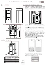
13 ADVANCED HYDRAULIC DIAGRAMS
In case the type of system diagram designed requires
the management of the 3-way valve (diagram 1
and 3), it is necessary to purchase an optional kit at
a Nobis authorized sales point or technician.
13.1 DIAGRAM 01
(DHW TANK + HEATING)
The following diagram can be used when a boiler
without a plate heat exchanger is in use and the
User wants to buy an accumulator (boiler) to be con-
nected to the circuit, in order to produce domestic
hot water. In this kind of circuit, the room temperature
is managed by the remote control which, having a ra-
dio connection, acts as a remote chronothermostat.
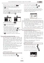
STAND-BY SCREEN
1
2
It shows boiler water actual temperature as detected
by the probe. Moreover, temperature settings – edi-
table by using – can be shown by pressing
scroll buttons.
Any change is confirmed either automatically - within
3 seconds from the last change – or by pressing
button. An acoustic signal will confirm the change.
OK
1
2
It shows the DHW storage temperature as detected
by the probe. Temperature settings – editable by
pressing – can be shown by pressing scroll
buttons. Any change in temperature settings is confir
-
med either automatically - within 3 seconds from the
last change – or by pressing button. An acoustic
signal will confirm the change.
OK
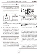
The operation is the same as the one described in the
basic diagram, with the only difference that, here the
product exchanges directly in the DHW storage (prio-
rity); when the set temperature is reached, the three-
way valve changes its position and the appliance
begins to exchange in the heating circuit. From this
moment on, heating can be managed by using the
remote control to set the room temperature as well
as H
2
O temperature (see diagram 00 operation re-
lated to modulation, eco stop, etc.). The three-way
valve redirects itself to the DHW storage when:
- it is required by the storage tank itself;
- it is required by the flow switch
(optional, if connected)
From ECOSTOP or H
2
O STANDBY status, the product
restarts considering heating or DHW accumulator
settings.
By setting SUMMER mode, the three-way valve
remains fixed, allowing heat produced by the
appliance to be transferred only inside the DHW
storage tank. As soon as this condition is reached,
the product switches to ECO STOP mode.
The DHW storage is managed by the appliance thanks
to a contact or immersion probe (not provided) to be
connected on the back side of the product.
The new stand-by screen is shown below.
To go back to the STAND-BY screen, press
button
repeatedly
The turbulators are activated automatically each
time the appliance is switched on/off and by means
of a timer during operation. It never occurs when the
machine is not active.
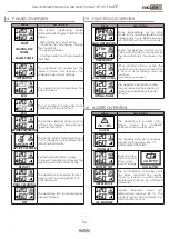
When you pass from one screen to another, you
display the following screen for a few seconds:
GENERAL INFORMATION NOTE:
This screen indicates the handheld device is trying
to communicate with the appliance, a useful
operation to recover information to display to the
end user.
If communication is absent, the writing FIELD followed
by a number appears. In this case, simply approach
the appliance to re-establish
communication.
1
2
1
2


