6 Installation
NivuLink Micro - Rev. 02/13.11.2018
page 37
6.6.3.2
Typical wiring schemes
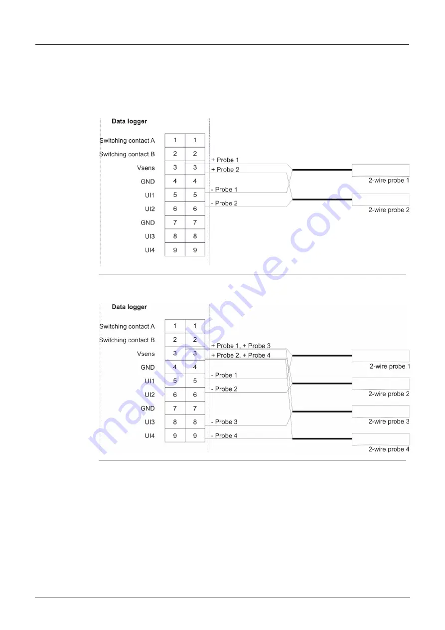
The wiring diagrams below illustrate typical wiring schemes with sensors and / or
actuators. For the colors of the cables and cores, please refer to the user manuals
for the sensors / actuators.
Fig. 6-9: Connecting 2 x 2-wire probes to the NivuLink Micro
Fig. 6-10: Connecting 4 x 2-wire probes to the NivuLink Micro


