background image

2.Installation

2-1.Connection

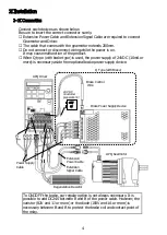
Connect each devices as shown below.
Be sure to insert the correct connector surely.

※ The cable that comes with the gearmotor extends 200mm.
※ Do not connect or disconnect wiring while the power is on.

It may cause malfunction of the product.

Extension Power Cable and Extension Signal Cable are required to connect
Gearmotor and Driver.

When Q type (with brake type) is used, the power supply of 24VDC (10mA or
more) is necessary aside from optional brake power supply device.

To ON・OFF the brake, our regular option is not always necessary. It is
possible to add DC24V between B and B of the power cable. However, the
varistor (82V and 1J or more) or the diode (100V and 1A or more) is
necessary between B and B to protect the brake coil and contact point of
the relay.

Brake Power Supply Device

Brake Control
 Wire

APQ Gearmotor

Regenerative Resistor

Extension
Power Cable

Extension
Signal Cable

APQ Driver

Power Supply
Cable

+24V

0V

24 VDC
(customer
preparation)

Q Type (with Brake)

4

Summary of Contents for GTR-AR APQ

Page 1: ...APQ Type Gearmotor Instruction Manual...

Page 2: ...nd inspection of the equipment should have enough knowledge and technical skill for the product Failure to observe this warning may cause explosion spark fire electric shock physical injury and or dam...

Page 3: ...Before coupling with the other machine be sure to check the direction of rotation Unexpected operation in wrong direction may cause serious injury and or damage to the equipment Before servicing disc...

Page 4: ...crews or nuts are not loose 4 Components a Gearmotor b Instruction Manual c Accessory The ordered products and the contents indicated in the nameplate are correct Type Reduction ratio Motor capacity V...

Page 5: ...the power supply of 24VDC 10mA or more is necessary aside from optional brake power supply device To ON OFF the brake our regular option is not always necessary It is possible to add DC24V between B...

Page 6: ...ing the designated key materials This product can be installed in any direction due to a grease lubrication system The displacements and differ according to the type of coupling Therefore they should...

Page 7: ...sitioned in the reverse direction so that the load point moves to the shaft edge When attaching be sure to smear extreme pressure agent molybdenum disulfide etc on the surface of driven shaft and the...

Page 8: ...is already clarified positioning spacer is not necessary By having a positioning spacer smoother detachment from the hollow shaft can be obtained For more details about the detachment from the hollow...

Page 9: ...at the detachment from the hollow shaft 45 M6 M6 M8 M10 M12 30 25 20 35 Make sure to avoid excessive force between the casing and the hollow shaft Smoother detachment can be obtained by using a jig as...

Page 10: ...ctly coupled with the flange face of the other machine the alignment should be done precisely to avoid burnout of motor damage to the bearings etc caused by misalignment In the AF3 Series there is a b...

Page 11: ...no radial load suspending load imposed between the driven shaft and the hollow shaft of the reducer caused by poor alignment between the hole of fixing part and the connecting machine Refer to the Fig...

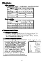
Page 12: ...ff Brake on Type Spring Close m All models use grease lubricant without needing replacement or replenishment The gear motor has been designed for an approximate use life of 10 000 hours Length of Moto...

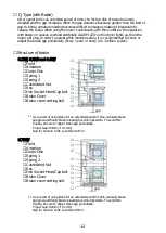
Page 13: ...ake gap periodically As a result of using brake for an extended period of time naturally brake gap grew and finally brake releasing become impossible To avoid this trouble be sure to adjust brake gap...

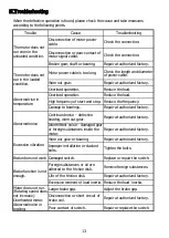
Page 14: ...oad inertia Adjust the brake gap Repair at authorized factory Tighten the bolts Repair at authorized factory Worn out gear or bearing Reduce the frequency Repair at authorized factory Repair at author...

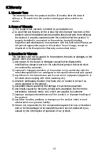
Page 15: ...to the equipments which are not produced by us caused by the interruption of operation of our product any repairs to the losses or damages caused by the disassemble modification change of parts or th...

Page 16: ...i 444 1297 JAPAN TEL 81 566 92 5312 FAX 81 566 92 7002 ver 1 0 2010 4 If you have any questions or concerns about our product please contact the dealer or distributor from whom purchased or contact th...

Reviews: