USER MANUAL
16
33014816(1)2005-07 A
PERIODICAL CHECKS
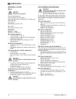
Battery
Check the electrolyte level.
Check the battery poles for oxidation.
Clean the entire surface of the battery with a damp sponge.
Tyre pressure
Front wheels
Recommended pressure: 7 Bar
Rear wheels
Recommended pressure: 7 Bar
Fluid levels
Brake fluid:
DOT4
Hydraulic oil: ROTRA ATF
Skirt closing adjustment
–
Loosen the locknut (1, Fig. M).
–
Adjust the fastener, making sure that the skirt closing
panel closes hermetically.
–
Adjust the skirt spring (2, Fig. M) pressure with the
mounting screw.
Parking brake adjustment
–
Loosen or pull the nut (1, Fig. N) avoiding to move the
cable end.
–
Adjusting the cable tension, make sure the brake is not
locked.
Gear pump hydraulic oil filter replacement
–
Empty the tank.
–
Remove the tank (1, Fig. O) cover.
–
Unscrew the filters (1, Fig. P) from their seats inside the
tank.
–
Screw the new filters into place using the appropriate
wrench (50) and reinstall the tank cover.
–
Screw the drain plug.
–
Check the oil level and top it up if necessary.
Variable delivery pump hydraulic oil filter
replacement
1.
Unscrew the mounting screw (1, Fig. Q).
2.
Unscrew the filter and place it in a container designed for
special waste. Replace it with an original filter.
EXTRAORDINARY MAINTENANCE
For the engine maintenance, please follow the instructions
provided in the Use and Maintenance Manual concerning the
engine installed on the sweeper. This manual comes in a
special case.
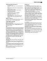
Side seal replacement
–
Remove the mounting screws (1, Fig. R) and the seal
holder (2).
–
Fit the new seal with the seal holders, so that the seal
slightly touches the ground.
–
Tighten the mounting screws.
Main broom replacement
–
Remove the right side lid.
–
Remove the mounting screws and the seal holder.
–
Move the seal sideways.
–
Remove the split pin (1, Fig. S).
–
Remove the support (2, Fig. S).
–
Remove the broom (3, Fig. S).
–
Install the broom (3, Fig. S).
–
Install the support (2, Fig. S).
–
Reinstall the split pin (1, Fig. S).
–
Reinstall the seal.
–
Close the lid.
Main broom (print on ground) adjustment
If the main broom is left rotating for a few minutes when the
machine is stationary, the print left on the ground is useful to
adjust the broom itself.
–
If the print size is less then 40 mm or more than 100 mm,
adjust the spring pressure with the mounting nut (1, Fig.
T).
Side broom replacement
–
Unscrew the mounting screw (1, Fig. U).
–
Remove the broom.
–
Unscrew the support mounting screws.
–
Replace the broom and reinstall the mounting screws.
–
Secure the broom to the motor.
Side broom adjustment
–
Adjust the broom pressure with the setscrew (1, Fig. V).
Rear seal replacement
–
The seal should touch the ground lightly and evenly.
–
To replace the seal, remove the mounting nuts (1, Fig.
W).
–
Remove the seal holder.
–
Replace the seal and reinstall.
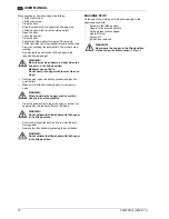
WARNING!
Wear gloves and goggles.
WARNING!
Do not pollute the environment with used oils
and filters.
WARNING!
Do not pollute the environment with used oils
and filters.
WARNING!
Any maintenance operation should be carried
out with the machine off.
Wait for all the parts to stop and cool down.
Summary of Contents for SR 1700 2WD B
Page 3: ...33014816 1 2005 07 A B C ...
Page 4: ...D E 1 1 2 16 18 17 4 14 11 3 8 6 10 9 6 8 7 12 13 15 5 ...
Page 85: ...33014816 1 2005 07 A J 14 13 12 8 11 10 3 3 4 5 6 7 3 16 1 2 9 8 15 ...
Page 86: ...33014816 1 2005 07 A K L M N O P 1 1 1 1 2 1 1 ...
Page 87: ...33014816 1 2005 07 A Q R S T U V 1 3 1 2 1 1 1 1 2 ...
Page 88: ...33014816 1 2005 07 A W X Y Z AA AB AC 1 1 1 1 1 1 ...
Page 89: ...33014816 1 2005 07 A AD ...
Page 90: ...33014816 1 2005 07 A AE ...
Page 91: ...33014816 1 2005 07 A AF ...
Page 92: ......
Page 93: ...33014816 1 2005 07 A F 2 1 11 4 6 8 7 12 9 5 10 3 ...
Page 94: ...G 3 5 8 7 4 6 11 1 12 9 2 10 13 ...
Page 95: ...33014816 1 2005 07 A H I 10 12 2 3 7 9 4 1 5 11 8 4 1 5 11 8 2 9 13 10 12 3 7 6 6 ...

