


.
USB
.
VI Basic Operations
5 Using the DS-L1 when Connected to a PC by a USB Cable
- 114 -
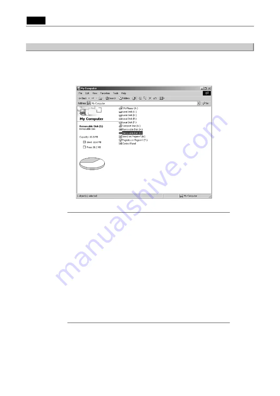
5.3.2
Outline of the Disk Drive
When the DS-L1 is connected to a PC, the disk drive for the CF card, etc., and the internal image
drive of the DS- L1 are each recognized as one removable disk by the PC.
When the DS-L1 is connected to a PC, two removable disks are displayed in [My Computer] on
your PC’s desktop.
The drive names of the removable disks differ with each PC environment.
NOTE: In the following cases, there might be a conflict between another connected
device and the drive letter.
• When media is inserted correctly into position, the message “Please insert
media” is displayed when you click the icon for the media drive
• A similar message is displayed when you click the icon for the CCD image
drive.
• Connecting the DS-L1 will immediately disable all other USB devices
connected to the PC.
In such a case, change the drive letter assigned to the media drive or the
CCD image drive.
The following shows how to make this change.
(1)
Select [Start] – [Control Panel] – [Administrative Tools] – [Computer
Management] – [Disk Management].
(2)
Right-click the volume whose drive letter you want to change and select
[Change the drive letter and path].
(3)
Click [Edit] and choose one of unassigned drive letters from the select box
or enter a drive letter directly from the keyboard and click [OK].
(4)
Click [OK] in the ensuing confirmation dialog box.
Summary of Contents for DS-5M
Page 2: ......