LLE14BRDA001A/E
7 - 17
7.3.1.5 Position of carriage ASSY. left/right shaft
Purpose: Performing position adjustment and calibration of the left/right shaft using the left/
right shaft adjustment jig after adjusting the height and
θ
axis of the carriage ASSY. Y axis.
Jig: Left/right shaft adjustment jig LEDJ-16(40396-M001)
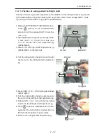
1. Display the SYSTEM SETTING MODE screen.
Press
(DATA) on the CALIBRATION
screen to set the carriage ASSY. X axis free
(see 7.5.1).
2. After adjusting the height of the carriage ASSY.
Y axis (see 7.3.1.3) and the
θ
axis (see
7.3.1.4), remove the Y axis adjustment jig
(40396-M002).
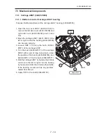
3. Attach the left/right shaft adjustment jig
(40396-M001) to the left shaft.
4. Turn the timing belt by hand to move the right
shaft close to the left/right shaft adjustment
jig.
5. Loosen HH4 × 6 (n = 2) fixing the gear stopper
(44001-M541).
6. Turn the right shaft by hand to align its pin to
the notch of the left/right shaft adjustment jig.
7. Tighten HH4 × 6 (n = 2) with the right shaft
inserted in the left/right shaft adjustment jig.
8. Press
to perform initialization and confirm
again that the right shaft is inserted into the
left/right shaft adjustment jig smoothly.
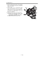
9. Remove the left/right shaft adjustment jig.
(40396-M001)
Left shaft
Timing belt
Right shaft
541
2
HH4×6
Summary of Contents for Le 1000
Page 1: ...PATTERNLESS EDGER Model SERVICE MANUAL June 2008 Pages in total 152 LLE14BRDA001A E...
Page 8: ...This page is intentionally left blank LLE14BRDA001A E 1 2...
Page 10: ...This page is intentionally left blank LLE14BRDA001A E 2 2...
Page 19: ...LLE14BRDA001A E 3 9 3 3 Model Configuration...
Page 22: ...LLE14BRDA001A E 3 12 5 4 01 000000 9CVGT RTGUUWTG CZ M2C EU area only...
Page 28: ...LLE14BRDA001A 3 18...
Page 34: ...LLE14BRDA001A E This page is intentionally left blank...
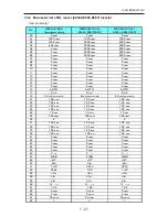
Page 91: ...LLE14BRDA001A E 7 27 7 4 2 Parameter list of BL motor 40340 E066 E067 inverter User parameter...
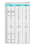
Page 92: ...LLE14BRDA001A E 7 28 User parameter...
Page 93: ...LLE14BRDA001A E 7 29 System parameter...
Page 126: ...LLE14BRDA001A E 8 2 8 2 Connector Cable...
Page 127: ...LLE14BRDA001A E 8 3...
Page 128: ...LLE14BRDA001A E 8 4...
Page 129: ...LLE14BRDA001A E 8 5...
Page 130: ...LLE14BRDA001A E 8 6...
Page 131: ...LLE14BRDA001A E 8 7 44401 BA01 2 2 2 2 2 2 2 2 2 2 2 44401 BA01 MAIN BOARD 2 2 2...
Page 134: ...LLE14BRDA001A E 8 10 8 5 Grease MSDS 8 5 1 NIPPECO LLP...
Page 135: ...LLE14BRDA001A E 8 11...
Page 140: ...LLE14BRDA001A E 8 16 8 5 4 NBU15...
Page 141: ...LLE14BRDA001A E 8 17...
Page 142: ...LLE14BRDA001A E 8 18...
Page 143: ...LLE14BRDA001A E 8 19...
Page 144: ...LLE14BRDA001A E 8 20...
Page 145: ...LLE14BRDA001A E 8 21 8 6 Troubles and Measures...
Page 146: ...LLE14BRDA001A E 8 22...
Page 147: ...LLE14BRDA001A E 8 23...
Page 148: ...LLE14BRDA001A E 8 24...
Page 149: ...LLE14BRDA001A E 8 25...
Page 152: ...LLE14BRDA001A E 8 28 This page is intentionally left blank...


