III
7.3 Mechanical Components ..................................................................................... 7-13
7.3.1 Carriage ASSY. (44401-5000) .................................................................... 7-13
7.3.1.1 Rattle removal of carriage ASSY. bearing ........................................ 7-13
7.3.1.2 Engagement of X axis motor ASSY. motor gear .............................. 7-14
7.3.1.3 Height of carriage ASSY. Y axis ........................................................ 7-15
7.3.1.4
θ
axis of carriage ASSY. Y axis ......................................................... 7-16
7.3.1.5 Position of carriage ASSY. left/right shaft ......................................... 7-17
7.3.2 Lens measurement unit ASSY.................................................................... 7-18
7.3.2.1 Feeler ASSY. height .......................................................................... 7-18
7.3.2.2 Initial position of feeler ASSY. ........................................................... 7-19
7.3.2.3 Voltage of lens measurement unit ASSY. ......................................... 7-19
7.3.3 Safety beveling/grooving ASSY. (44001-6000) ......................................... 7-21
7.3.3.1 Position of safety beveling/grooving ASSY. arm .............................. 7-21
7.3.4 Chuck pressure .......................................................................................... 7-22
7.3.4.1 Tentative chuck pressure .................................................................. 7-22
7.3.4.2 Chuck pressure ................................................................................. 7-23
7.3.5 Tracing unit (43401-4000) .......................................................................... 7-24
7.3.5.1 Tilt of tracing unit stylus ..................................................................... 7-24
7.3.5.2 Position of cable CA63...................................................................... 7-24
7.3.5.3 Cleaning of pattern tracing pin .......................................................... 7-25
7.4 Electrical Components ......................................................................................... 7-26
7.4.1 Parameters BL motor inverter .................................................................... 7-26
7.4.2 Parameter list of BL motor (40340-E066, E067) inverter .......................... 7-27
7.4.3 Trip table of BL motor inverter .................................................................... 7-30
7.5 Calibration ............................................................................................................ 7-31
7.5.1 Displaying calibration screen ..................................................................... 7-31
7.5.2 Attaching calibration jig............................................................................... 7-31
7.5.3 Calibration of safety beveling/grooving ASSY. .......................................... 7-32
7.5.4 Wheel calibration ........................................................................................ 7-33
7.5.5 Calibration of lens measurement unit ASSY. ............................................. 7-34
7.5.6 Torque calibration of tracing unit ................................................................ 7-35
7.5.7 Frame auto calibration of tracing unit ........................................................ 7-35
7.5.8 Pattern auto calibration of tracing unit ....................................................... 7-35
7.5.9 Full calibration of tracing unit ..................................................................... 7-36
7.6 Processing Adjustment ........................................................................................ 7-38
7.6.1 Feeler axis .................................................................................................. 7-38
7.6.2 Finish size ................................................................................................... 7-41
7.6.3 Bevel position ............................................................................................. 7-41
7.6.4 Lens axis..................................................................................................... 7-42
7.6.5 Polish (differential, polishing wheel height, bevel, axis) ............................ 7-44
7.6.5.1 Polish (differential, polishing wheel height) ...................................... 7-44
7.6.5.2 Bevel position to be polished ............................................................ 7-45
7.6.5.3 Flat polish axis ................................................................................... 7-47
7.6.5.4 Bevel polish axis ............................................................................... 7-48
7.6.5.5 Polycarbonate polish differential ....................................................... 7-49
7.6.5.6 Polish size ......................................................................................... 7-49
7.6.6 Groove ........................................................................................................ 7-50
7.6.6.1 Groove depth .................................................................................... 7-50
7.6.6.2 Groove position ................................................................................. 7-51
Summary of Contents for Le 1000
Page 1: ...PATTERNLESS EDGER Model SERVICE MANUAL June 2008 Pages in total 152 LLE14BRDA001A E...
Page 8: ...This page is intentionally left blank LLE14BRDA001A E 1 2...
Page 10: ...This page is intentionally left blank LLE14BRDA001A E 2 2...
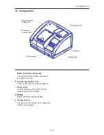
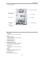
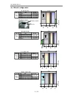
Page 19: ...LLE14BRDA001A E 3 9 3 3 Model Configuration...
Page 22: ...LLE14BRDA001A E 3 12 5 4 01 000000 9CVGT RTGUUWTG CZ M2C EU area only...
Page 28: ...LLE14BRDA001A 3 18...
Page 34: ...LLE14BRDA001A E This page is intentionally left blank...
Page 91: ...LLE14BRDA001A E 7 27 7 4 2 Parameter list of BL motor 40340 E066 E067 inverter User parameter...
Page 92: ...LLE14BRDA001A E 7 28 User parameter...
Page 93: ...LLE14BRDA001A E 7 29 System parameter...
Page 126: ...LLE14BRDA001A E 8 2 8 2 Connector Cable...
Page 127: ...LLE14BRDA001A E 8 3...
Page 128: ...LLE14BRDA001A E 8 4...
Page 129: ...LLE14BRDA001A E 8 5...
Page 130: ...LLE14BRDA001A E 8 6...
Page 131: ...LLE14BRDA001A E 8 7 44401 BA01 2 2 2 2 2 2 2 2 2 2 2 44401 BA01 MAIN BOARD 2 2 2...
Page 134: ...LLE14BRDA001A E 8 10 8 5 Grease MSDS 8 5 1 NIPPECO LLP...
Page 135: ...LLE14BRDA001A E 8 11...
Page 140: ...LLE14BRDA001A E 8 16 8 5 4 NBU15...
Page 141: ...LLE14BRDA001A E 8 17...
Page 142: ...LLE14BRDA001A E 8 18...
Page 143: ...LLE14BRDA001A E 8 19...
Page 144: ...LLE14BRDA001A E 8 20...
Page 145: ...LLE14BRDA001A E 8 21 8 6 Troubles and Measures...
Page 146: ...LLE14BRDA001A E 8 22...
Page 147: ...LLE14BRDA001A E 8 23...
Page 148: ...LLE14BRDA001A E 8 24...
Page 149: ...LLE14BRDA001A E 8 25...
Page 152: ...LLE14BRDA001A E 8 28 This page is intentionally left blank...


