background image

12

Installation guide - ORTHOBLOC 3000

3996 en - 2019.03 / n

4.2 - Torque arm kit

4.2.1 - Torque arm mounting

Screw the torque arm (17) on the fi xing side and machinery by 

using screws (195) class 8.8 minimum (according to NFE 27-

005). Centre torque arm. Place the pin.

The screws must be stopped by an anaerobic adhesive (Loctite 

Freinfi let normal 243 for example). This adhesive must resist 

to  vibrations  and  may  allow  dismounting  of  torque  arm  if 

necessary.

Braking torque of fi xing screws

Tighten screws simultaneously and progressively.

4.2.2 - Torque arm exploded view/parts list

195

17

213

281

All the bolts must be screwed up to 70% of their 

elastic strength.

Ot 3132 to Ot 3533 Ot 3633, Ot 3733

Ot 3833

Ot 3933

Rep

Description

Qty

Qty

Qty

Qty

17 Torque arm

1

1

1

1

195 Torque arm fi xing screw

3

4

8

10

213 Pin

1

1

2

2

281 Flexible mounting

1

1

1

1

4.3 - Hollow shaft

1-

  Check  that  the  cylindrical  shaft  has  been  machined  in 

accordance with standard NF - E 22 - 175, with a slide fi t: g6, 

(the hub is: H7).

2 -

 Check that the key is standard and the shaft is the minimum 

length tapped at the end (O.Z).

3 -

 Before mounting, degrease all the parts, taking care not to 

splash any solvent on the seals.
Use grease (PAO compound) to lubricate any parts in contact, 

to avoid corrosion.

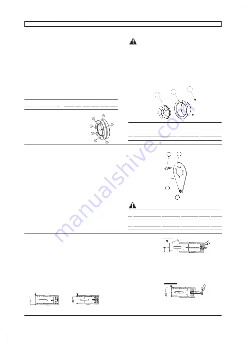
  Fixing on an untapped shaft          Fixing on a shouldered shaft

Mounting

Mounting should be performed as described in the procedure 

above, without jolting.

The gearbox is mounted on the machine shaft using a threaded 

rod, screwed into the shaft.

By screwing the nut down onto the washer, the shaft is 

smoothly inserted into the cylindrical hub.

Dismantling

Use  a  spanner  with  a  diameter  corresponding  to  the  shaft 

thread and turn until the shaft comes out.

4 - ASSEMBLY OF THE OPTIONS

4.1 - Shrink-disc Ot 3132 to Ot 3933

4.1.1 - Mounting

Remove the cover. Remove all grease from shaft and hollow 

shaft bore.

1 -

 Lightly oil the seating of the shrink-disc on the hollow shaft.

2 -

 Draw shrink-disc onto hollow shaft. Slide shaft and hollow 

shaft into one another.

3 -

 Tighten diametrically opposed clamping screws by hand 

whilst aligning the shrink-disc so that the clamping fl anges lie 

parallel to each other.

Tighten  the  shrink  disc  screws,  increasing  the  torque  very 

progressively to tightening torque indicated in the chart bellow.  

It is  normal that each screw must be tightened several times 

until the torque is obtained.

Ot 31 to 34 Ot 35 Ot 36

Ot 37

Ot 38

Ot 39

Tightening torque for bolts of shrink-disc 

Tightening torque for bolts of shrink-disc 

Tightening torque for bolts of shrink-disc 

Tightening torque for bolts of shrink-disc (N.m)

(N.m)

12

30

30

59

100

100

Ø shrink disc screws

M6

7xM8 10xM8 12xM10 10xM12 12xM12

Do not tighten “cross-shaped” but “in one rotation”, starting at 

the top right and following sketch bellow.

Tighteness of shrink disc screws to be controlled 

periodically.

Dismantling

1 -

 Part-release the clamping screws evenly in stages in order 

to avoid any tilting of the clamping fl anges whilst taking great 

care  for  safety  reasons  that  the  clamping  screws  are  not 

completely released from the thread bore as the pretensions in 

the shrink-disc could cause the discs to jump apart.

2 -

 Draw the shrink-disc off the hollow shaft, and if applicable, 

clean oxidizing on shaft and hollow shaft bore.

4.1.2 - Shrink-disc exploded view/parts list

302

016

204

Ot 3132 to Ot 3733

Ot 3833, Ot 3933

Rep

Description

Qty

Qty

16 Shrink disc cover

1

1

204 Cover fi xing screw

2

4

302 Shrink disc

1

1

O ring seal

O ring seal

O ring seal

O ring seal

DRIVE SYSTEMS - ORTHOBLOC 3000

Summary of Contents for LEROY-SOMER ORTHOBLOC 3000

Page 1: ...THOBLOC 3000 RTHOBLOC 3000 RTHOBLOC Guide d installation Installation guide Inbetriebnahme Instalación Systèmes d entraînement Drive systems Antriebssysteme Sistemasdeaccionamiento 3996 lg 2019 03 n es en de ...

Page 2: ......

Page 3: ...fr ORTHOBLOC 3000 RTHOBLOC 3000 RTHOBLOC Guide de mise en service et d entretien Systèmes d entraînement Référence 3996 fr 2019 03 n ...

Page 4: ...es risques pouvant entraîner des dommages matériels ou corporels Malgré tout le soin apporté à la fabrication et au contrôle de ce matériel LEROY SOMER ne peut garantir à vie l absence de fuite de lubrifiant Aucasoùdelégèresfuitespourraientavoirdesconséquencesgravesmettantenjeulasécuritédesbiensetdespersonnes il appartient à l installateur et à l utilisateur de prendre toutes les précautions nécess...

Page 5: ...raisser les roulements des moteurs équipés de graisseurs Contrôler l entrefer des moteurs frein Huile roulements joints 6 mois Ajuster niveau d huile Inspecter les joints 3 ans ou 5 000 h Vidanger et renouveler l huile minérale Changer les joints Changer la graisse des roulements regraissables 5 ans ou 25 000 h Vidanger et renouveler l huile synthétique Changer les joints Changer la graisse des ro...

Page 6: ...B7 2 1 552 2 2 95 2 1 9 2 3 752 2 6 4 2 10 82 J11 22 15 AD AD AD AD AD AD J11 345 AD AD AD AD AD AD J11 40 75 AD AD AD AD AD AD xx 5 4 5 5 5 5 5 5 5 2 8 8 2 8 2 11 2 11 2 2 8 2 8 2 11 11 11 B8 B53 B3 12 12 4 1 95 4 1 742 3 3 54 3 6 1 3 8 42 J10 18 2 J10 23 7 J10 333 J10 66 6 6 5 5 5 5 5 5 5 5 2 2 3 4 4 3 10 10 10 10 2 2 3 2 2 2 10 2 11 10 V5 V1 V6 6 0 93 6 1 65 5 1 25 5 3 3 5 5 1 6 5 1 J4 13 5 J4 ...

Page 7: ... 8 J5 10 J5 11 J5 10 5 NC 1 Tolérance 0 05 litre pour quantité d huile 5 litres Fonctionnement avec anti dévireur AD nous consulter 2 pour quantité d huile 5 litres NC nous consulter En cas de fonctionnement en position inclinée autre nous consulter 3 4 Quantité d huile Ot Cb combinés Ot combinés Ot Sortie i Cb Entrée Position de fonctionnement B3 B5 litres1 B6 B52 litres1 B8 B53 litres1 B7 B54 li...

Page 8: ...ntage Prendre une vis dont le diamètre correspond au taraudage de l arbre et visser pour extraire l arbre 4 MONTAGE DES OPTIONS 4 1 Frette de serrage Ot 3132 à Ot 3933 4 1 1 Montage Démonter le capot Dégraisser l alésage du moyeu et l arbre 1 Huiler légèrement les composants ne pas utiliser d huile avec additif au bisulfure de molybdène ou haute pression ni de graisse 2 Insérer l assembleur expans...

Page 9: ...ORTHOBLOC 3000 RTHOBLOC 3000 RTHOBLOC Installation guide Drive systems Reference 3996 en 2019 03 n en ...

Page 10: ...terial or physical damage Despite all the care taken in the manufacture and checking of this equipment LEROY SOMER cannot guarantee that lubricant will not escape during the product s lifetime If slight leaks could have serious consequences for the safety of people and property the installer and user should take all necessary precautions to avoid such consequences CONTENTS 1 INSTALLATION RECOMMEND...

Page 11: ...softhemotorsfittedwithgreasenipples Control the air gap of brake motors Oil seals bearings 6 months Adjust oil level Inspect the seals 3 years or 5 000 h Drain and refill mineral oil Change the seals Change the grease of regreasable bearings 5 years or 25 000 h Drain and refill synthetic oil Change the seals Change the grease of regreasable bearings Grease nipple on AP Ot 35 Replace the grease ISO VG...

Page 12: ...3 752 2 6 4 2 10 82 J11 22 15 AD AD AD AD AD AD J11 345 AD AD AD AD AD AD J11 40 75 AD AD AD AD AD AD xx 5 4 5 5 5 5 5 5 5 2 8 8 2 8 2 11 2 11 2 2 8 2 8 2 11 11 11 B8 B53 B3 12 12 4 1 95 4 1 742 3 3 54 3 6 1 3 8 42 J10 18 2 J10 23 7 J10 333 J10 66 6 6 5 5 5 5 5 5 5 5 2 2 3 4 4 3 10 10 10 10 2 2 3 2 2 2 10 2 11 10 V5 V1 V6 6 0 93 6 1 65 5 1 25 5 3 3 5 5 1 6 5 1 J4 13 5 J4 19 2 J4 27 5 xx 2 2 2 2 2 ...

Page 13: ...LS In case of operating position in another inclined plan consult LS 3 4 Oil quantity combined Ot Cb Combined Ot Ot Output i Cb Input Operating position B3 B5 litres1 B6 B52 litres1 B8 B53 litres1 B7 B54 litres1 V5 V1 litres1 V6 V3 litres1 Ot S BS Cb Ot NS Cb Ot S BS Cb Ot NS Cb Ot S BS Cb Ot NS Cb Ot S BS Cb Ot NS Cb Ot S BS Cb Ot NS Cb Ot S BS Cb Ot NS Cb 3935 191 17900 3433 2 3 T xx 3 3 xx 7 5 ...

Page 14: ... the shaft comes out 4 ASSEMBLY OF THE OPTIONS 4 1 Shrink disc Ot 3132 to Ot 3933 4 1 1 Mounting Remove the cover Remove all grease from shaft and hollow shaft bore 1 Lightly oil the seating of the shrink disc on the hollow shaft 2 Draw shrink disc onto hollow shaft Slide shaft and hollow shaft into one another 3 Tighten diametrically opposed clamping screws by hand whilst aligning the shrink disc...

Page 15: ...ORTHOBLOC 3000 RTHOBLOC 3000 RTHOBLOC Inbetriebnahme Antriebssysteme Referenz 3996 de 2019 03 n de ...

Page 16: ... Trotz sorgfältigster Überwachung von Fertigung und Kontrolle des beschriebenen Getriebes kann LEROY SOMER nicht auf Lebensdauer garantieren dass keine Leckagen des Schmiermittels auftreten Bei Anwendungen bei denen ein leichtes Austreten von Schmiermittel schwerwiegende Folgen für die Sicherheit von Gegenständen und Personen haben könnte obliegt es dem Installateur und dem Betreiber alle notwendi...

Page 17: ...chmiernippel gemäß Vorschrift schmieren Bei Bremsmotoren den Luftspalt überprüfen Öl Dichtungen Lager 6 monate Schmiermittelniveau auffüllen Dichtungen kontrollieren 3 Jahre oder 5000 h Mineralöl ablassen und erneuern Dichtungen austauschen Fett der nachschmierbaren Lager austauschen 5 Jahre oder 25000 h Synthetiköl ablassen und erneuern Dichtungen austauschen Fett der nachschmierbaren Lager austa...

Page 18: ... 1 552 2 2 95 2 1 9 2 3 752 2 6 4 2 10 82 J11 22 15 AD AD AD AD AD AD J11 345 AD AD AD AD AD AD J11 40 75 AD AD AD AD AD AD xx 5 4 5 5 5 5 5 5 5 2 8 8 2 8 2 11 2 11 2 2 8 2 8 2 11 11 11 B8 B53 B3 12 12 4 1 95 4 1 742 3 3 54 3 6 1 3 8 42 J10 18 2 J10 23 7 J10 333 J10 66 6 6 5 5 5 5 5 5 5 5 2 2 3 4 4 3 10 10 10 10 2 2 3 2 2 2 10 2 11 10 V5 V1 V6 6 0 93 6 1 65 5 1 25 5 3 3 5 5 1 6 5 1 J4 13 5 J4 19 2...

Page 19: ...enge 5 Liter Betrieb mit RücklaufsperreAD Kontaktieren Sie LS 2 bei einer Ölmenge 5 Liter 1 Toleranz 0 05 Liter bei einer Ölmenge 5 Liter 2 bei einer Ölmenge 5 Liter 1 Toleranz 0 05 Liter bei einer Ölmenge 5 Liter 2 bei einer Ölmenge 5 Liter 2 bei einer Ölmenge 5 Liter NC Kontaktieren Sie LS Bei einem Betrieb in anderer Schräglage wird Kontaktieren Sie LS 3 4 Ölmenge Ot Cb Doppelgetriebe Ot Doppel...

Page 20: ... Stösse in die zylindrische Nabe gezogen Demontage EineSchraubeverwenden derenDurchmesserderGewinde bohrung der Welle entspricht und eindrehen um die Welle herauszuziehen 4 MONTAGE DER OPTIONEN 4 1 Schrumpfscheibe Ot 3132 bis Ot 3933 4 1 1 Montage Die Abdeckhaube entfernen Die Bohrung der Nabe und die Welle entfetten 1 Die Komponenten leicht schmieren weder Öl mit einem Zusatz von Molybdänbisulfid ...

Page 21: ...ORTHOBLOC 3000 RTHOBLOC 3000 RTHOBLOC Instalación Sistemasdeaccionamiento Referencia 3996 es 2019 03 n es ...

Page 22: ...asionar lesiones corporales o daños materiales A pesar de todas las precauciones to madas p ara fabricar y comprobar este material LEROY SOMER no puede garantizar de por vida la ausencia de fugas de lubricante En caso de que leves pérdidas puedan acarrear consecuencias graves que perjudiquen la seguridad de bienes y personas el instalador y el usuario deben tomar todas las precauciones necesarias ...

Page 23: ... los rodamientos de los motores equipados con engrasadores Comprobar el entrehierro de los motores freno Aceite juntas rodamientos 6 meses Ajustar el nível de aceite Inspectar las juntas 3 años o 5 000 h Vaciar y renovar el aceite mineral Cambiar las juntas Cambiar la grasa de los rodamientos reengrasadables 5 años o 25 000 h Vaciar y renovar el aceite sintético Cambiar las juntas Cambiar la grasa...

Page 24: ...B7 B54 B7 2 1 552 2 2 95 2 1 9 2 3 752 2 6 4 2 10 82 J11 22 15 AD AD AD AD AD AD J11 345 AD AD AD AD AD AD J11 40 75 AD AD AD AD AD AD xx 5 4 5 5 5 5 5 5 5 2 8 8 2 8 2 11 2 11 2 2 8 2 8 2 11 11 11 B8 B53 B3 12 12 4 1 95 4 1 742 3 3 54 3 6 1 3 8 42 J10 18 2 J10 23 7 J10 333 J10 66 6 6 5 5 5 5 5 5 5 5 2 2 3 4 4 3 10 10 10 10 2 2 3 2 2 2 10 2 11 10 V5 V1 V6 6 0 93 6 1 65 5 1 25 5 3 3 5 5 1 6 5 1 J4 1...

Page 25: ... Funcionamiento con antiretorno AD consultar LS 2 para cantidad de aceite 5 litros NC consultar LS En caso de funcionamiento en otra posición inclinada consultar LS 3 4 Cantidad de aceite Ot Cb combinados Ot combinados Ot Salida i Cb Entrada Posición de funcionamiento B3 B5 litros1 B6 B52 litros1 B8 B53 litros1 B7 B54 litros1 V5 V1 litros1 V6 V3 litros1 Ot S BS Cb Ot NS Cb Ot S BS Cb Ot NS Cb Ot S...

Page 26: ...oscado atornillado en el eje Atornillando la tuerca que se apoya en la arandela se inserta el eje en el hueco cilíndrico sin golpe Desmontaje Tomar un tornillo cuyo diámetro corresponda al taladro del eje y atornillar para extraer el eje 4 MONTAJE DE LAS OPCIONES 4 1 Anillos de apriete Ot 3132 a Ot 3933 4 1 1 Montaje Retirar la caperuza de chapa Limpiar el eje 1 Lubricar levemente los componentes ...

Page 27: ...25 NOTES ...

Page 28: ...Moteurs Leroy Somer Headquarter Boulevard Marcellin Leroy CS 10015 16915 ANGOULÊME Cedex 9 Limited company with capital of 65 800 512 RCS Angoulême 338 567 258 www leroy somer com ...

Reviews: