background image

Cooler Removal

Shut off water to the cooler, and disconnect the water input and output lines from the 
cooler. 

Note: The cooler can usually be removed by two methods; removing the cooler by slid-
ing it out from the cooler housing, or by removing the cooler housing with the cooler 
in place. See your drawings for details.

Removing the cooler leaving the cooler housing in place:

1.   

Disconnect and remove the cooler RTDs and leak detector.

2.   

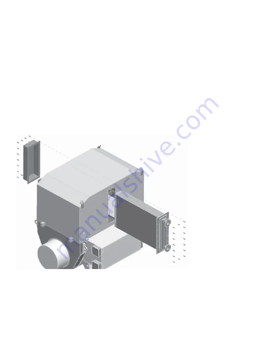
Remove the fasteners that attach the cooler cover on the non inlet/outlet side.

3.   

Remove the fasteners that attach the cooler on the inlet/outlet side. 


See Figure 3. 

4.   

If your generator cooler is attached to a drip tray, remove the fasteners.


Figure 3

Bolt removal for cooler cover and cooler

5.   

Slide the cooler out of the cooler housing. Attach a hoist with chains or a strap  


suitable for lifting the cooler. See the cooler weight on your drawings or the  


cooler plate. See Figure 4.

This manual show a vertically posi-
tioned cooler. Removal of a horizontally 
mounted cooler is basically the same. 
refer to the drawing section in your 
Instruction Manual.

Use safe lifting practices to avoid dam-
age to the cooler or injury to personnel. 
See the cooler weight on your draw-
ings or the cooler plate

CAUTION
The cooler is a delicate part. Be careful 
not to cause tube and fi n damage on 
the cooler. Damage may cause leakage 
or loss of cooling ability.

Summary of Contents for 22765-01

Page 1: ...e original manufacture of this equipment Modifications implemented after shipment from Kato Engineering are not represented in this documentation and are not supported by Kato Engineering Kato Enginee...

Page 2: ......

Page 3: ......

Page 4: ......

Page 5: ...Generators Large Electric Motors Specifications Unless otherwise noted all specifications are specified at 21 C 70 F 24 Vdc power supply gap set to 1 27 mm 50 mils and using Metrix AISI 4140 steel tar...

Page 6: ...ct Inputs Product Outputs 4 20 mA proportional to Shaft relative vibration or Shaft Position Vibration TXR 0 3 mils 0 75 um pk pk 0 5 mils 0 125 um pk pk 0 10 mils 0 250 um pk pk Position TXA 20 80 mi...

Page 7: ...9 meters 0 5 8 mm 3 11 mm 0 20 to 80 mils 1 20 to 160 mils or TXR 39 Probe Series System Length Tip Diameter 4 20 mA Range 5 5 meters 7 7 meters 0 5 mm For Series 3309 NSv or Replacement for RAM Serie...

Page 8: ...ation Condition Monitoring and Protection PROXIMITY PRODUCTS Proximity Probe Transmitter Trendsetter Model TXR Radial and TXA Axial 1 23 Cross Reference from 5465 5488 to Trendsetter TXR TXA For negat...

Page 9: ...ut voltage that is directly proportional to the distance between the probe tip and the observed conductive surface The system can measure both static position and dynamic vibration data Its primary us...

Page 10: ...300 XL NSv Proximitor Sensor refer to Specifications and Ordering Information p n 147385 01 2 XL 8mm probes provide a thicker encapsulation of the probe coil in the molded PPS plastic probe tip to pro...

Page 11: ...45 0 50 1 0 7 59 0 50 1 5 7 73 0 50 2 0 7 88 0 50 Probe Length m Resistance from the Center Conductor to the Outer Conductor 5 0 8 73 0 70 9 0 9 87 0 90 Table 2 Extension Cable DC Resistance Length of...

Page 12: ...e 0 to 10 kHz 0 3 dB with up to 305 metres 1000 feet of field wiring Minimum Target Size 15 2mm 0 6 in diameter flat target Shaft Diameter Minimum 50 8mm 2 in Recommended minimum 76 2mm 3 in When gapp...

Page 13: ...lvanic isolators Certificate number 1109248 LR 26744 222 3300 XL Proximitor Sensor and probe nA Ex nA IIC T4 T5 Class I Zone 2 or Class I Division 2 Groups A B C and D when installed without barriers...

Page 14: ...to 232 C T2 51 C to 177 C T3 51 C to 120 C T4 51 C to 80 C T5 51 C to 40 C Hazardous Area Conditions of Safe Use ATEX Follow the conditions of safe use included on the Declaration of Conformance sent...

Page 15: ...1 Probe case torque 5 1 N m 45in lb recommended 7 3 N m 65 in lb maximum Connector to connector torque Refer to the following table Recommended Torque Table 6 Recommended Torque Connector Type Tighten...

Page 16: ...alues may erode the tip assembly of the probe causing media to leak into surrounding areas Bently Nevada Inc will not be held responsible for any damages resulting from leaking 3300 5 mm proximity pro...

Page 17: ...inimum unthreaded length 0 0 0 0in Example 0 4 0 4in B Overall Case Length Option Order in increments of 0 1in Threaded Length configurations Maximum case length 9 6 9 6in Minimum case length 0 8 0 8i...

Page 18: ...andard cable 11 Miniature coaxial ClickLoc connector with connector protector FluidLoc cable 12 Miniature coaxial ClickLoc connector FluidLoc cable E Agency Approval Option 00 Not required 05 Multiple...

Page 19: ...nnector Protector Kit for 3300 5mm probes including connector protectors and installation tools 136536 01 Connector Protector Adapter Makes connector protector kits purchased prior to 1998 compatible...

Page 20: ...Graphs Figure 1 Typical 3300 5mm probe and 1 metre of cable at high and low temperatures XL Proximitor Sensor and XL extension cable are at 25 C Part Number 172036 Rev K 05 16 Page 12 of 16...

Page 21: ...Figure 2 3300 5 metre XL Proximitor Sensor at high temperatures 3300 5mm probe and XL extension cable at 25 C Part Number 172036 Rev K 05 16 Page 13 of 16...

Page 22: ...diameter of armor 9 0mm 0 35in maximum diameter of armor ferrule 6 Miniature male coaxial connector 7 23mm 0 285 in maximum outside diameter D 7 3 2 0 13in 8 Unthreaded length A 9 Case length B 10 6 0...

Page 23: ...0mm 11 8in less than cable length See Note 5 4 75 cable 3 7mm 0 15 in maximum outside diameter 3 9mm 0 16in maximum diameter for FluidLoc cable 7 6mm 0 30in maximum outside diameter or armor 9 0mm 0 3...

Page 24: ...probes PFA jacket on non armored portion for ETR probes 6 Probes ordered with 5 or 9 metre integral cables have a length tolerance of 20 0 7 Five metre probes are designed for use with the five metre...

Page 25: ......

Page 26: ......

Page 27: ......

Page 28: ......

Page 29: ......

Page 30: ......

Page 31: ......

Page 32: ......

Page 33: ......

Page 34: ......

Page 35: ......

Page 36: ......

Page 37: ......

Page 38: ......

Page 39: ......

Page 40: ......

Page 41: ......

Page 42: ......

Page 43: ......

Page 44: ......

Page 45: ......

Page 46: ......

Page 47: ......

Page 48: ......

Page 49: ......

Page 50: ......

Page 51: ......

Page 52: ......

Page 53: ......

Page 54: ......

Page 55: ......

Page 56: ......

Page 57: ......

Page 58: ......

Page 59: ......

Page 60: ......

Page 61: ......

Page 62: ......

Page 63: ......

Page 64: ......

Page 65: ......

Page 66: ......

Page 67: ......

Page 68: ......

Page 69: ......

Page 70: ......

Page 71: ......

Page 72: ......

Page 73: ......

Page 74: ......

Page 75: ......

Page 76: ......

Page 77: ......

Page 78: ......

Page 79: ......

Page 80: ......

Page 81: ......

Page 82: ......

Page 83: ......

Page 84: ......

Page 85: ......

Page 86: ......

Page 87: ......

Page 88: ......

Page 89: ......

Page 90: ......

Page 91: ......

Page 92: ......

Page 93: ......

Page 94: ......

Page 95: ......

Page 96: ......

Page 97: ......

Page 98: ......

Page 99: ......

Page 100: ......

Page 101: ......

Page 102: ......

Page 103: ......

Page 104: ......

Page 105: ......

Page 106: ......

Page 107: ......

Page 108: ......

Page 109: ......

Page 110: ......

Page 111: ......

Page 112: ......

Page 113: ......

Page 114: ......

Page 115: ......

Page 116: ......

Page 117: ......

Page 118: ......

Page 119: ......

Page 120: ......

Page 121: ......

Page 122: ......

Page 123: ......

Page 124: ......

Page 125: ......

Page 126: ......

Page 127: ......

Page 128: ......

Page 129: ......

Page 130: ......

Page 131: ......

Page 132: ......

Page 133: ......

Page 134: ......

Page 135: ......

Page 136: ......

Page 137: ......

Page 138: ......

Page 139: ......

Page 140: ......

Page 141: ......

Page 142: ......

Page 143: ......

Page 144: ......

Page 145: ......

Page 146: ......

Page 147: ......

Page 148: ......

Page 149: ......

Page 150: ......

Page 151: ......

Page 152: ......

Page 153: ......

Page 154: ......

Page 155: ......

Page 156: ......

Page 157: ......

Page 158: ......

Page 159: ......

Page 160: ......

Page 161: ...Instruction Manual Water to Air Cooler Maintenance for Kato Generators Publication 350 11111 00 April 2012...

Page 162: ...Table of Contents Description Cleaning the Cooler Cooler Removal Cooler Installation Torque Chart...

Page 163: ...Figure 1 Typical Kato generator equipped with a water to air cooler...

Page 164: ...water flowing through heat exchanger tubes Flange connections provide water input and discharge connections The typical air cooler assembly consists of the following Air cooler housing sheet metal Coo...

Page 165: ...he leakage cham bers which are located behind the water boxes Leakage Chambers The two leakage chambers are connected by a tube The leakage chamber on the flange side has a tell tale connector that ca...

Page 166: ...esh water 1 A mechanical method may be necessary if other methods are not effective If build up is such that the cooler cannot be cleaned and the generator overheats contact Kato Engineering service d...

Page 167: ...ee Figure 3 4 If your generator cooler is attached to a drip tray remove the fasteners Figure 3 Bolt removal for cooler cover and cooler 5 Slide the cooler out of the cooler housing Attach a hoist wit...

Page 168: ...ching the cooler housing to the generator See Figure 5 Attach a hoist and chains to the cooler housing and lift the cooler housing off of the generator See Figure 6 In the examples shown the drip tray...

Page 169: ...attach the cooler housing to the generator Lifting points Figure 6 Remove the cooler housing Use safe lifting practices to avoid dam age to the cooler or injury to personnel See the cooler weight on...

Page 170: ...the cooler hood 2 Slide the cooler into the hood Insert the fasteners to hold the cooler to the cooler hood 3 Attach the fasteners on the non inlet outlet side and attach the cooler cover 4 Tighten al...

Page 171: ...es Grade 5 Grade 8 Foot Pound Foot Pound Newton Meter Newton Meter Grade 5 GASKETED COVERS SCREW SIZE Grade 2 Foot Pounds Newton Meter Newton Meter Foot Pound Inch pounds Ft Lbs Tol N M Tol Ft Lbs Tol...

Page 172: ...Standard AC Generator Single or Two Bearing Drive End Air Discharge Publication 350 01001 00 B 01 2019 Kato Engineering Inc P O Box 8447 Mankato MN USA 56002 8447 Tel 507 625 4011 KatoEngineering mai...

Page 173: ...anges in designs and processes and the variability of Kato Engineering s products information in this manual must not be regarded as binding and is subject to change without notice The image on the fr...

Page 174: ...Before Startup 23 Operation 24 Initial startup 24 Restoring Residual Magnetism Field Flashing 25 Continuous Operation 26 Idling 27 Parallel Operation 27 Maintenance 29 Schedules 29 Maintenance Proced...

Page 175: ...ected to Regulator 25 Guide to Allowable Phase Unbalance 26 Synchronizing Paralleled Generators with Test Lamps 28 Example Rectifier Form May Vary 35 Testing the Rotating Rectifier with an Ohmmeter 36...

Page 176: ...of equipment the following paragraphs define warnings cautions and notes as they are used in this manual WARNING Warnings identify an installation operating or maintenance procedure practice condition...

Page 177: ...of copper or aluminum rods that are inserted through each pole surface and are brazed to copper or aluminum damper end plates at each end of the lamination stack The end plates are brazed to adjacent...

Page 178: ...er armature and the rotating rectifier The exciter armature assembly contains steel laminations that are stacked and keyed on the shaft or on to a sleeve which is keyed to the generator shaft A three...

Page 179: ...steel laminations The laminations are held in place by steel compression rings and are welded to the frame bars of the exciter PMG frame The PMG windings are placed in slots in the laminations Insulat...

Page 180: ...re placing the generator in operation see the maintenance section Protect generators operating intermittently in very damp locations with space heaters Slowly warm generators placed in operation after...

Page 181: ...asuring the flywheel to the flywheel housing as shown in Figure 2 See Table 1 for maximum allowable runout NOTE Mounting of the indicators must allow complete rotation of the prime mover Use dial indi...

Page 182: ...0 076 3 16 125 410 0 004 0 102 2 17 625 448 0 004 0 102 1 20 125 511 0 005 0 127 0 5 23 000 584 0 005 0 127 0 25 500 648 0 006 0 152 00 31 000 787 0 007 0 178 Check the engine flywheel s radial and fa...

Page 183: ...to a different location check alignment before startup WARNING Do not pry on the generator fan blades Blades can weaken which could result in serious injury or death from flying debris NOTE Generator...

Page 184: ...gine flywheel following the manufacturer s recommended procedures and in accordance with engine manufacturer s specifications Check the coupling s radial and face runout by mounting a dial indicator t...

Page 185: ...er for parallel alignment Flywheel Figure 7 Alignment Check Following the final generator adjustment and runout check remove the horizontal shims from the adaptor flywheel housing and move the generat...

Page 186: ...he position of the dial button on the face of the opposite coupling half as shown in Figure 3 Rotate both shafts simultaneously keeping the finger or button on the indicator at the reference mark on t...

Page 187: ...arter revolution A variation of readings at different positions will indicate how the machine needs to be adjusted to obtain a maximum misalignment of 0 005 0 127 mm TIR Compensation for engine therma...

Page 188: ...ed with the generator If the dimensions do not match move the rotor axially relative to the stator until the dimensions are equal Check the engine flywheel housing pilot s radial face and runout by mo...

Page 189: ...hub If Y is more than G remove spacers between the drive discs and generator hub Figure 12 Single Bearing Generator Drive Plate and Adaptor S Y W A Adaptor Bolt holes Drive plates Fan Shaft Install th...

Page 190: ...ury or death from flying debris Figure 13 SAE Flywheel and Adapter B C G Tapped bolt holes Flywheel Figure 14 Disc to Flywheel Installation Flywheel Drive plates Drive hub Spacer Bolt Lock washer Ensu...

Page 191: ...nd move it out of the way See Figure 15 After attaching the drive discs to flywheel bolts align the fan hub to the mark to move the fan back to its original position Ensure the key is fully in place u...

Page 192: ...ame and positioning of the probe on the shaft as shown in Figure 16 If the total indicated runout exceeds 0 003 0 0762 mm remove the drive discs bolts and rotate the generator relative to the engine f...

Page 193: ...local regulations and national international electrical code requirements Check the electrical diagrams provided with the generator or manual The main terminals need to be properly spaced for the loa...

Page 194: ...revolution to see if the rotor turns freely Check the bearings to see they are properly lubricated Determine the direction of the engine rotation and make sure that it matches the rotation of the gen...

Page 195: ...ibration levels at no load and rated load A slight increase is normal As the load is maintained for 2 3 hours the vibration levels will gradually increase and reach a final level Units with Automatic...

Page 196: ...a 12 or 24 volt battery to the exciter field coil circuit and flash as follows 1 Open the output circuit breaker and stop the engine 2 Disconnect the exciter field coil wires EF1 at the terminal EF1...

Page 197: ...vertical line determined by the maximum current in any of the phases and expressed in percent of rated current crosses the horizontal line determined by the minimum current in any of the phases and e...

Page 198: ...tude is the same and frequency meters indicate whether the frequencies are the same Whether the voltages are in phase and exactly at the same frequency is indicated by a synchroscope or by synchronizi...

Page 199: ...enerator is in phase the lights will be dark close the circuit breaker Immediately after closing the breaker measure the line current kVAR of the generator The readings must be within the rating of th...

Page 200: ...s and insulation for cracking or damage Check all exposed electrical connections for tightness Check transformers fuses capacitors and lightning arrestors for loose mounting or physical damage Check a...

Page 201: ...e Every 30 000 Hours or 5 Years of Operation Disassemble the generator this includes rotor removal Clean the generator windings using either depending upon the severity of contamination compressed air...

Page 202: ...nsulation Physical damages can be caused by physical shock vibration over speed short circuit forces or line starting out of phase paralleling erosion by foreign matter damage by foreign objects and t...

Page 203: ...ust has been removed a small brush can be affixed to the vacuum nozzle to loosen and allow removal of dirt that is more firmly attached After the initial cleaning with a vacuum compressed air may be u...

Page 204: ...G armature stator Exciter Armature 1 Disconnect the exciter armature leads from the rotating rec tifiers 2 Connect the leads of the exciter armature to one clamp of a 500 volt Megger and connect the o...

Page 205: ...e and location of the unit available equipment and experience of personnel Before drying remove the voltage regulator and cover all inlet and discharge openings Provide an opening at the top of the ma...

Page 206: ...to 250 F 121 C Regreasable Ball or Roller Bearings In applications where regreasable bearings are used grease fill fittings and relief valves are incorporated into the bearing housing Lubricate the be...

Page 207: ...eshift test lamp consisting of standard flashlight batteries and a flashlight and built as shown in Figure 22 across the surge protector in either direction If the light comes on the surge protector i...

Page 208: ...on one end and around the shaft on the opposite end Lift up the rotor and move it out resting the rotor as the slings are moved down the pipe for the next lifting stage IMPORTANT The following procedu...

Page 209: ...ard PMG assemblies use a locknut to secure the PMG rotor See Figure 26 To remove the PMG rotor with a lock nut a On the lockwasher pry up the tab that is bent down in a notch of the locknut Then unscr...

Page 210: ...Page 39 Figure 25 Pulling the Armature Assembly Plate Hydraulic jack Threaded rod Exciter sleeve Figure 26 PMG Rotor with Locking Nut Lock washer and tab Locknut...

Page 211: ...val 1 Remove the endbracket s to expose the bearing s 2 Use a puller to remove the bearing from the shaft end with a cap If the bearing is going to be used again make sure the puller supplies pressure...

Page 212: ...mature and PMG Installation See Figure 24 1 Clean the shaft and inside of the exciter sleeve 2 Place the key in the slot in the shaft 3 Lay the generator field wires flat in the wireway with the wire...

Page 213: ...air gap of the armature is less than specified in Table 4 or if the air gap of the PMG is less than 0 020 0 5 mm check a generator engine alignment b bearing wear c misalignment of the armature PMG o...

Page 214: ...of approximately normal room temperature Protect the shaft from corrosion by applying an anti corrosion agent Cover the unit with a durable cover Prepare units that cannot be stored in a temperature a...

Page 215: ...e Ft lb Tolerance N m Tolerance Ft lb Tolerance N m Tolerance Ft lb Tolerance N m Tolerance 4 40 4 0 5 5 0 6 6 32 8 0 9 10 1 1 8 32 20 2 3 16 1 8 21 2 4 10 24 18 2 0 24 2 7 10 32 34 3 8 33 3 7 33 3 7...

Page 216: ...16 x 2 00 80 13 108 18 144 13 195 32 196 40 266 53 249 40 338 68 M18 x 2 50 114 22 155 29 190 22 258 50 269 50 365 70 344 50 466 70 M20 x 2 50 162 23 220 30 260 23 353 50 366 60 496 50 486 60 659 66 M...

Page 217: ...one bridge If open in field coils remove exciter field assembly and return assembly to factory for repair Loss of residual magnetism in exciter field poles Restore residual magnetism or flash field Wh...

Page 218: ...assembly Replace defective fuses or rectifiers Excessive load Reduce load to rated value Defective bearing Replace the bearing Improper speed of engine driven generator set due to defective governor i...

Page 219: ...ller For pulling exciter armature Standard tools Cable tool Crimping Flashlight As required Grease gun For lubricating bearings Hammer Soft faced Lamp incandescent Safety light Screwdrivers Standard s...

Page 220: ...49 Figure 28 Main Part Location Typical Exciter stator Rectifier Exciter armature Endbracket Rotor Stator windings Feet Bearing Coupling hub Adapter Fan Drip proof cover Exciter cover Lead connection...

Page 221: ...neering Support The brand you trust the power you depend on Include the serial number and model number for your machine in the email subject line Field Service KatoService mail nidec com Manuals KatoM...

Page 222: ...16 7 86 3 95 418 86 54 2 BEARING 17 9 84 6 87 1789 47 147 9 18 8 66 5 25 820 38 87 5 19 8 66 4 25 664 12 70 8 15981 336 COUPLING HUB 142 25 57029 69 3493 8 2685490 15062 ADDED TOTAL TOTAL WK lb in 27...

Page 223: ...5 40 6 50 2 08E 01 25 8 14 24 99 20 47 6 14E 01 78 7 15 19 96 10 01 1 22E 01 24 5 16 19 96 10 03 1 23E 01 24 6 BEARING 17 24 99 17 45 5 24E 01 67 1 18 22 00 13 34 2 40E 01 39 7 19 22 00 10 80 1 94E 01...

Page 224: ......

Page 225: ......

Page 226: ......

Page 227: ......

Reviews: