background image

4

 – English

EN

3

3

3

13

8

A

14

D

G

D

H

E

H

F

F

5

4

6

1

B
C

G

12

2

2

7

11

2

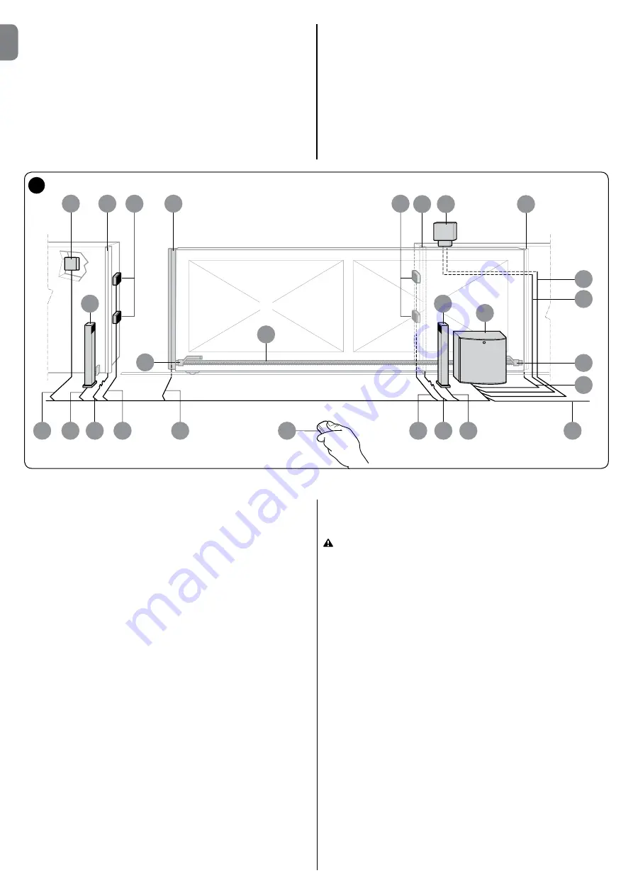
2.3 - Typical system

The 

figure 2

 below indicates a typical sliding gate automation system using 

the TUB4000.

1

Key operated selector switch

2

Photocell on post

3

FOTO photocells

4

Main fixed edge (optional)

5

Main moveable edge

6

“Open” stop bracket

7

Rack

8

Secondary fixed edge (optional)

9

Flashing light

10

Aerial

11

Motor

12

“Closed” stop bracket

13

Secondary moveable edge (optional)

14

Radio transmitter

2.4 - Installation of the gear motor

If a base for the gear motor already exists, fixing must be performed directly to 

the surface by means of expansion bolts.
If this is not so, it is necessary to:

01.

 Dig an adequately large foundation hole.

02.

 Prepare one or more conduits for the electrical cables as shown in 

fig. 5

.

03.

 Assemble the four clamps on the foundation plate setting one nut under-

neath and one on top of the plate as in 

fig. 3

 so that the threaded section 

protrudes out of the plate as much as possible.

04.

 Pour the concrete and, before it starts to harden, set the foundation plate 

checking that it is parallel to the leaf and perfectly level as shown in 

fig. 5


Wait for the concrete to harden completely.

05.

 Remove the body from the gear motor following the procedure shown in 

fig.7

 in reverse order.

06.

 Place the gear motor on top of the foundation plate and make sure it is 

perfectly parallel to the leaf, then secure it by tightening the 4 nuts with 

washers to the respective clamps as shown in 

fig. 6

.

07.

 Release the pinion as shown in the “Release and manual movement” para

-

graph in the Chapter “Instructions and Warnings for users of the TUB4000 

gear motor”.

08.

 Open the leaf up completely and place the first piece of the rack on the pi

-

nion and check that the beginning of the rack corresponds to the beginning 

of the leaf. Make sure that there is at least 2÷3 mm of play between the rack 

and the pinion, then fasten the rack to the leaf using suitable means.

09.

 Slide the leaf, using the pinion as a reference point for the fastening the 

other elements of the rack.

10.

 Cut away any excess of the rack.

11.

 Open and close the gate several times and make sure that the rack is ali-

gned with the pinion with a maximum tolerance of 10- 15 mm. Moreover, 

check that the play of 2-3 mm between the pinion and the rack has been 

respected along the entire length.

12.

 Fix the two “Opening” and “Closing” limit switch brackets with the relative 

dowels to the outer sides of the rack as shown in 

fig. 4

. Considering that 

the leaf will slide for a further 2÷3 cm after the limit switches have activated, 

the brackets should be positioned at a sufficient distance from the mecha

-

nical stops.

13.

 Perform the operation described in point 7 in reverse and block the pinion.

14.

 Secure the body to the TUB4000 as shown in 

fig. 7

 and ensure that the 

limit switch lever positioned above the pinion moves freely.

15.

 Close the gear motor door and make sure that the safety microswitch po-

sitioned to the right of the electric motor is activated.

 In order to prevent the weight of the leaf from affecting the gear 

motor, it is important that there is a play of 2÷3 mm between the rack 

and the pinion.

2.5 - Installation of the various devices to the control unit.

Perform the installation of all foreseen devices following the respective instruc-

tions. Check in Chapter 7 (DPRO500) which devices can be connected to the 

TUB4000.

CAUTION! – The electrical connections must be performed by skilled 

and  qualified  personnel  in  strict  observance  of  current  legislation, 

standards and regulations with the system disconnected from elec-

tricity supply.

Summary of Contents for TUB4000

Page 1: ...installazione e l uso FR Instructions et avertissements pour l installation et l utilisation ES Instrucciones y advertencias para la instalaci n y el uso DE Installierungs und Gebrauchsanleitungen und...

Page 2: ......

Page 3: ...airs or adjustments are necessary because a failure with the installation or an incorrectly balanced automated system may lead to injury The packing materials of the product must be disposed of in com...

Page 4: ...he website of the European Community Special warning to ensure the continued compliance with the requirement It is essential that the other materials used in the installation such as electrical cables...

Page 5: ...kg or up to 30 m long according to the data shown in Table 1 below TABLE 1 Length of leaf in metres Maximum cycles hour Up to 5 42 5 10 21 10 15 14 15 20 10 20 25 8 25 30 7 0 0 5 10 15 20 25 30 35 40...

Page 6: ...t piece of the rack on the pi nion and check that the beginning of the rack corresponds to the beginning of the leaf Make sure that there is at least 2 3 mm of play between the rack and the pinion the...

Page 7: ...ecessary in particular applications See the instructions manual for the advised type of connection if there is more than one edge Note 5 Special devices which enable connection even when the leaf is m...

Page 8: ...6 English EN V W U L1 L2 L3 1 2 3 NDA040 4 5 6 1 2 3 A Neutral wire from the supply plug...

Page 9: ...Check that all the instructions in the Installation warnings chapter have been rigorously complied with 2 Using the control devices transmitter push button key switch etc test the Opening Closing and...

Page 10: ...essories for other brands contact the motor manufacturer 5 7 11 m Cable for FLASHING LIGHT with aerial 2 x 1 mm2 for 230 V AC flashing light RG58 type shielded cable aerial 10 m PHOTOCELL cable 4 x 0...

Page 11: ...nose pliers 03 Insert the jumper 1 x 230 V 04 Re insert the top cover 7 4 Description of the electrical connections Fig 14 power supply safety and control devices and accessories You can connect contr...

Page 12: ...ut for the earth connection for the control unit and motors IMPORTANT We DO NOT recommend that you connect any device or accessory not mentioned in this instruction manual The manufacturer declines al...

Page 13: ...only for motors with mechani cal limit switches leave uncon nected with motors which have electronic limit switches LIMIT SWITCH mechanical limit switch STOP STOP terminal used for 8K2 safety edge or...

Page 14: ...he position acquisition phase or by using the Oview programmer Command No 3 Open Command No 4 Close Command No 5 Stop Command No 6 Step by Step Condominium Command No 7 Step by Step High priority Comm...

Page 15: ...ection with that of the closing limit switch at the LIMIT SWITCH terminal Fig 14 The position recognition phase can be repeated at any time also after the installation 7 11 Operating modes CAUTION If...

Page 16: ...ng the testing phase as described below refers to a typical system 1 Check that all the instructions in the Installation warnings chapter have been rigorously complied with 2 Release the motor Check t...

Page 17: ...sages to identify their status and faults The following table describes the various alarm signals according to the type of problem These alarm signals are provided by appropriate flashes of the green...

Page 18: ...g SAFETY LED DIAGNOSTICS Signal Cause Solution On Correct operation Off Safety chain open The safety chain is made up of the series of inputs ALT Stop via button motor thermal protection motor release...

Page 19: ...slation in your area or return the product to the retailer when purchasing an equivalent product CAUTION Local legislation may include the application of heavy fines in the event of improper disposal...

Page 20: ...ble to partly completed machinery Annex II part 1 section B In addition the product conforms to the following directive in accordance with the provisions applicable to partly completed machinery Direc...

Page 21: ...ough the wired controls It is not possible to send commands via radio If the safety devices are out of order arrange to repair the automation as soon as possible Releasing and locking the gearmotor ma...

Page 22: ......

Reviews: