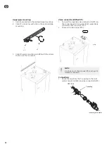


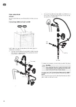


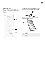


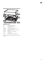

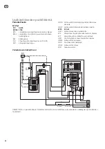


Connecting external additional heat
Connect external additional heat, via a potential-free
contact, to AA7-X2:6 (N) and AA7-X2:5 (230 V) in the
unit box (WP5-AA25).
1
2
3
4
5
6
AA7-X2
External
addition
External
AA25
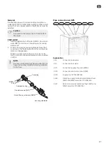
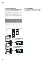
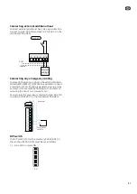
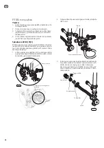
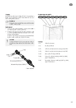
Connecting any emergency cooling
To prevent it becoming too hot in the external addition-
al heat ((EM1), (EM2),), (), (EP30) it is possible to connect
a cooling function. Cooling is generated using a relay
and occurs for example by flushing out hot water or
rerouting the circuit to a convector fan.
Connect relay for emergency cooling to AA5-X9:3 (N)
and AA5-X9:4 (230 V) in the unit box (WP5-AA25).
ON
1
2
3
4
5
6
7
8
-X9
-X2
24
20
21
22
23
15
16
17
18
19
10
11
12
13
14
5
6
7
8
9
1
1
N
L
PE
PE
1
2
3
4
5
6
7
8
2
3
4
5
6
7
8
9
2
3
4
-X8
-X4
-X10
-X1
N
L
AA25
External
Emergency
cooling
AA5-X9
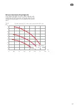
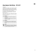
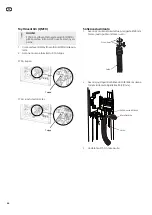
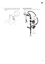
DIP switch
The DIP switch (S2) on the accessory board (AA5) in
the unit box (WP5-AA25) must be set as follows.
1, 2, 3, 4 and 6 in mode ON.
ON
1
2
3
4
5
6
7
8
S2
51
GB
Summary of Contents for SCA 41
Page 2: ......
Page 27: ...Elschema 27 SE...
Page 28: ...28 SE...
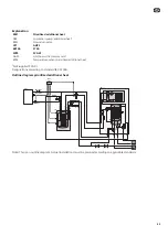
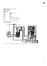
Page 53: ...Electrical circuit diagram 53 GB...
Page 54: ...54 GB...
Page 79: ...S hk kytkent kaavio 79 FI...
Page 80: ...80 FI...
Page 81: ...81 Elschema Wiring diagram S hk kytkent kaavio...
Page 82: ......
Page 83: ......
Page 84: ...NIBE AB Sweden Hannabadsv gen 5 Box 14 SE 285 21 Markaryd info nibe se www nibe eu 331140...


