


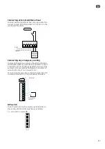


Electrical connection
NOTE
All electrical connections must be carried out
by an authorised electrician.
Electrical installation and wiring must be car-
ried out in accordance with the stipulations in
force.
The heat pump must not be powered when
installing SCA 41.
NOTE
If the supply cable is damaged, only NIBE, its
service representative or similar authorised
person may replace it to prevent any danger
and damage.
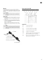
NOTE
To prevent interference, communication
and/or sensor cables to external connections
must not be laid closer than 20 cm from high
voltage cables.
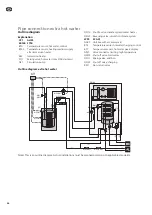
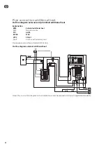
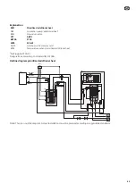
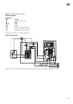
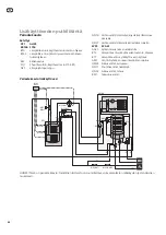
The electrical circuit diagram is at the end of this In-
staller manual.
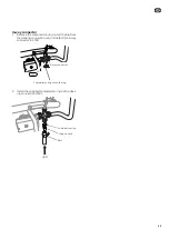
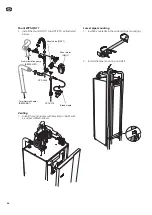
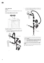
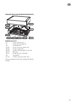
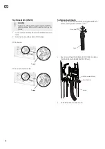
Installation of unit box (WP5-AA25)
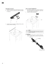
1. Drill a hole in the top panel on AHPSfor the ground
lead as illustrated below.
2. Remove the front panel and route the ground lead
through the panel.
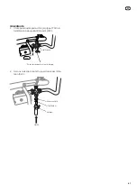
3. Install the enclosed tape to the bottom of the unit
box (AA25).
4. Install the unit box (AA25) on the panel. Secure
the ground lead in the screw at the front, right
corner, between the top panel and base.
5. Install the front panel on AHPS.
LEK
Ø 10 mm
47
GB
Summary of Contents for SCA 41
Page 2: ......
Page 27: ...Elschema 27 SE...
Page 28: ...28 SE...
Page 53: ...Electrical circuit diagram 53 GB...
Page 54: ...54 GB...
Page 79: ...S hk kytkent kaavio 79 FI...
Page 80: ...80 FI...
Page 81: ...81 Elschema Wiring diagram S hk kytkent kaavio...
Page 82: ......
Page 83: ......
Page 84: ...NIBE AB Sweden Hannabadsv gen 5 Box 14 SE 285 21 Markaryd info nibe se www nibe eu 331140...


