Conversion of F750
General
1. Shut off the heat pump and turn off the current
on the safety breaker.
2. Remove the front panels according to the descrip-
tion in the heat pump installation manual.
3. Drain F750 of water and release the pressure in
the climate system if the heat pump was previously
installed.
4. Disconnect the connection for incoming cold water,
see Installation manual for F750 for further instruc-
tions.
Mixer valve (FQ1)
F750 copper does not have mixer valve (FQ1). If the
factory setting is changed so that the hot water tem-
perature can exceed 60 °C install a mixer valve, see the
installation handbook for F750.
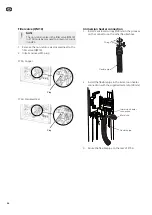
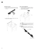
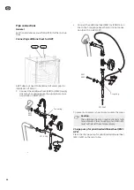
1. Between the mixer valve in F750 stainless (EB100-
FQ1) and the connector for incoming cold water
there is a flexible pipe. Detach this flexible hose
from the upper connection on the coupling.
LEK
Flexible pipe
Connection for incoming cold
water
Upper
connection
FQ1
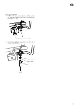
2. Plug the connection on the connector with the
supplied compression ring nut and plug (Ø15 mm).
Plug
Compression ring nut
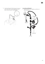
3. Remove the compression ring from the flexible
pipe by either knocking it out or using pliers to
compress it in different places until it detaches and
can be removed. Connect the supplied reduction
kit, support bush and the straight connector (22
mm) on the disconnected flexible hose and route
it to the rear of F750.
Straight
connection
Compression ring
Flexible pipe
Reduction kit
Support bush
FQ1
32
GB
Summary of Contents for SCA 41
Page 2: ......
Page 27: ...Elschema 27 SE...
Page 28: ...28 SE...
Page 53: ...Electrical circuit diagram 53 GB...
Page 54: ...54 GB...
Page 79: ...S hk kytkent kaavio 79 FI...
Page 80: ...80 FI...
Page 81: ...81 Elschema Wiring diagram S hk kytkent kaavio...
Page 82: ......
Page 83: ......
Page 84: ...NIBE AB Sweden Hannabadsv gen 5 Box 14 SE 285 21 Markaryd info nibe se www nibe eu 331140...


