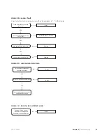
Function check, relays/compon-
ents
Relay location
Internal outputs
Output
K1 - On / On
Fan (GQ1).
K2 - High speed
K3
4-way valve (QN02).
K4
Solenoid valve fluid injec-
tion (QN30).
K5
Solenoid valve subcooling
(QN31).
K6
Compressor heater (EB10).
K7
Heater condensation
(EB11).
K8
Collar heater (EB13).
K9
Compressor (GQ10).
K10
Charge pump (Sometimes
referred to as circ. Pump)
(GP12).
K11
Alarm relay
Output
K12
External heating (EB14).
Stationary indication.
Stationary relay (on control
card)
Additional heat
Additional heat relay (on
control card)
NIBE™ F2300
Chapter 6 |
Troubleshooting
22
Summary of Contents for F2300
Page 1: ...Service manual LEK NIBE F2300 Air water heat pump SEM GB 1335 1 M11450 ...
Page 2: ......
Page 33: ...Electrical circuit diagram 31 Chapter 8 Technical data NIBE F2300 8 Technical data ...
Page 34: ...NIBE F2300 Chapter 8 Technical data 32 ...
Page 35: ...33 Chapter 8 Technical data NIBE F2300 ...
Page 36: ...NIBE F2300 Chapter 8 Technical data 34 ...
Page 42: ......
Page 43: ...NIBE AB Sweden Hannabadsvägen 5 Box 14 SE 285 21 Markaryd info nibe se www nibe eu ...


