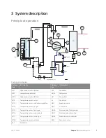
Principle of operation
BT16
BT28
BT17
BT14
BT15
BT13
BT12
BP1
BP2
BT10
M
EP1
EP2
QN2
GQ10
QN30
QN31
QN34
QN1
Underkylare
Avfrostningsprocess
HS1
Kapillärrör
Partikelfilter
Fläkt
0
)DQ
3DUWLFOH ILOWHU
50
41
&DSLOODU\ SLSH ~
(3
%7
%3
%7
*4
%3
(3
41
+6
%7
%7
%7
%7
%7
6XEFRROHU
41
41
41
&DSLOODU\ SLSH
%7
Cooling circuit diagram
Information
Designa-
tion
Information
Designa-
tion
Condenser
EP2
High pressure switch (29 bar)
BP1
Compressor
GQ10
Low pressure pressostat
BP2
Drying filter
HS1
High pressure switch (32 bar)
BP10
Fan motor
M
Temperature sensor, return
BT3
Expansion valve
QN1
Temperature sensor, condenser supply line
BT12
4-way valve
QN2
Temperature sensor, hot gas
BT14
Solenoid valve fluid injection
QN30
Temperature sensor, fluid pipe
BT15
Solenoid valve subcooling
QN31
Temperature sensor, evaporator in
BT16
Expansion valve, subcooler
QN34
Temperature sensor, suction gas
BT17
Non-return valve
RM1
Temperature sensor, ambient
BT28
Evaporator
EP1
7
Chapter 3 |
System description
NIBE™ F2300
3 System description
Summary of Contents for F2300
Page 1: ...Service manual LEK NIBE F2300 Air water heat pump SEM GB 1335 1 M11450 ...
Page 2: ......
Page 33: ...Electrical circuit diagram 31 Chapter 8 Technical data NIBE F2300 8 Technical data ...
Page 34: ...NIBE F2300 Chapter 8 Technical data 32 ...
Page 35: ...33 Chapter 8 Technical data NIBE F2300 ...
Page 36: ...NIBE F2300 Chapter 8 Technical data 34 ...
Page 42: ......
Page 43: ...NIBE AB Sweden Hannabadsvägen 5 Box 14 SE 285 21 Markaryd info nibe se www nibe eu ...


