background image

Commissioning and adjusting

Preparations

Before commissioning, check that the heating circuit is filled
and well vented. Check the pipe system for leaks.

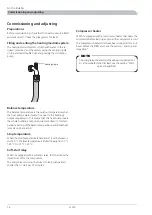
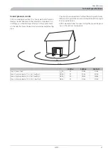
Filling and venting the heating medium system

The heating medium system is filled with water to the re-
quired pressure. Vent the system using the venting nipple
on the enclosed flexible hose and possibly the circulation
pump.

9HQWLQJ QLSSOH

Balance temperature

The balance temperature is the outdoor temperature when
the heat pump’s stated output is equal to the building’s
output requirement. This means that the heat pump covers
the whole building’s output requirement down to this tem-
perature. Setting of the balance temperature, additional heat,
is made on channel A5.

Stop temperature

When the stop temperature (channel A7) is set between -7
and -15 °C the flow temperature is limited linearly from -7 °C
/ 55 °C to -15 °C / 45 °C.

Soft-start relay

F2015 is equipped with a soft-start relay (97) that limits the
inrush current for the compressor.

The compressor must not be forced to start with periods
shorter than 1 start per 15 minutes.

Compressor heater

F2015 is equipped with a compressor heater that heats the
compressor before start-up and when the compressor is cold.

The compressor heater must have been connected for 6 - 8
hours before the FIRST start, see the section “Start-up and
inspection”.

NOTE

The compressor heater must have been connected for
6 – 8 hours before the first start, see the section “Start-

up and inspection”.

F2015

16

For the Installer

Commissioning and adjusting

Summary of Contents for F2015

Page 1: ...INSTALLATION AND MAINTENANCE INSTRUCTIONS MOS GB 1008 3 F2015 031239 F2015 LEK ...

Page 2: ......

Page 3: ...mp 14 Anti freeze function 14 External heat cable 14 Outside sensor 14 Thermostat control 15 Additional heat Downtime 15 Example of addition connection 15 External indication of main alarm 15 Commissioning and adjusting Preparations 16 Filling and venting the heating medium system 16 Balance temperature 16 Stop temperature 16 Soft start relay 16 Compressor heater 16 Start up and inspection 17 Read...

Page 4: ...n Start interval compressor A4 5 C Balance temperature A5 120 min Time delay addition relay A6 15 C Stop temperature A7 see page 22 Min interval between defrosting A8 0 C Start defrosting A9 10 C Stop defrosting A10 7 min Longest defrosting A11 Any changes in the basic settings are noted here Datum__________________________ Sign___________________________ See Component positions page 29 for locati...

Page 5: ...switching between room heating and hot water heating Accessories such as extra shunt group and pool control can be connected if SMO 10 is present F2015 can both heat hot water effectively at high outdoor temperatures and give a high output to the heating system at low outdoor temperatures If the outdoor temperature drops to a level below the stop temperature all heating must then occur with extern...

Page 6: ... water trough KVT 10 accessory is available for management and removal of condensation Strong wind combined with heavy snowfall can block the intake and exhaust air grilles Make sure that there is no snow on the grilles If necessary the outer casing can be cleaned using a damp cloth Care must be exercised so that the heat pump is not scratched when cleaning Avoid spraying water into the grilles or...

Page 7: ...mm Clearance in front of F2015 should be at least one metre F2015 must not be placed so that recircula tion of outdoor air can occur This causes lower output and impaired efficiency Control F2015 is equipped with an internal electronic controller that handles all functions necessary for heat pump operations Accordingly defrosting stop at max min temperature con nection of the compressor heater as ...

Page 8: ...the inlet i e the lower connection 71 HM in on F2015 All outdoor pipes must be thermally insulated with at least 19 mm thick pipe insulation The charge pump must be operational even if F2015 is not running to prevent damage due to freezing The charge pump can also be controlled directly from F2015 terminal block 11 which takes the outdoor temperature into consideration Alternatively the heat pump ...

Page 9: ...uded in F2015 Particle filter SF Shunt valve SV Safety valve SÄV Drain valve TV Outside sensor UG Heating thermostat VT Hot water sensor VVG F2015 docked with VVM 300 fixed condensing FIGHTER 2020 VVM 300 AV AV SÄV SF RC TV UG 990 F2015 6 8 and 11 can be connected to VVM 300 F2015 is controlled by VVM 300 F2015 works with floating con densing against the heating system and prioritises hot water ch...

Page 10: ...n pumps shunts etc F2015 works with floating condensing against the heating system and prioritises hot water charging via the three way valve VXV1 If F2015 cannot meet the heating requirement the oil fired boiler is started and additional heat is shunted in NOTE To prevent interference sensor cables and communic ation cables must be separated min 20 cm from high voltage cables when cable routing F...

Page 11: ...015 works with floating condensing against the heating system and prioritises hot water charging via three way valve VXV1 F2015 VP1 produces hot water If F2015 cannot meet the heating demand additional heat is shunted in from the oil fired boiler When additional heat is engaged hot water is heated using the immersion heater in the hot water heater NOTE To prevent interference sensor cables and com...

Page 12: ...ystem If F2015 cannot meet the heating requirement the additional heat is shunted in using the existing control equipment Additional heat can be blocked above the set balance tem perature by means of the automatic control system in F2015 In other cases the heat pump does not collaborate with the electric oil fired boiler in the optimum way Hot water production only takes place using the existing e...

Page 13: ...LVWLQJ FRQWURO HTXLSPHQW RRG ILUHG ERLOHU 99 F2015 charges the water heater accumulator tank VVB ACK When the firewood boiler is in use the heat pump and im mersion heater are disconnected when the temperature rises on the thermostat VT and start again when the temperature drops Self circulation through the heat pump is prevented by the check valve BV 11 F2015 For the Installer Docking ...

Page 14: ...n and wiring must be carried out in accord ance with the stipulations in force NOTE The live external control must be taken into considera tion when connecting QFRPLQJ VXSSO LEK Incoming feed cable is supplied and factory connected to terminal block X1 Approx 1 8 m cable is accessible outside the heat pump F2015 12 For the Installer Electrical connections ...

Page 15: ...reaking gap When the building is equipped with an earth fault breaker the heat pump should be equipped with a separate one Incoming supply must be 230 V 1AC 50Hz via distribution boards with fuses ႑ If an insulation test is to be carried out in the building disconnect the heat pump ႑ Connect control signal cable for thermostats to terminal 30 Cable type unscreened LiYY screened LiYCY Cable area at...

Page 16: ... 5 4 3 2 1 0 1 2 3 4 5 6 7 8 9 10 11 12 13 14 15 16 17 18 19 20 21 22 23 24 25 0 0LQXWHV SHU PLQXWHV 7HPSHUDWXUH NOTE There is a risk of freezing when the charge pump is connected to terminal block X11 11 and F2015 is deenergized FIGHTER 2020 EXTERNT Signal vid icke larm Signal vid larm Laddpump Extern värmekabel N N 230 V 3 4 1 X11 2 5 6 11 7 51 6LJQDO RQ QRQ DODUP 6LJQDOV LQ WKH HYHQW RI DODUPV ...

Page 17: ... relay terminal X201 14 This function is also activated when F2015 is deenergized If the outdoor temperature exceeds 35 C compressor oper ation is blocked and downtime is activated The connection to the additional relay is made as set out in the picture below FIGHTER 2020 EXTERNT 3 4 5 6 1 X201 Tillsatsvärme Stillestånd NO NC COM NO NC COM 2 14 7 51 GGLWLRQDO KHDW RZQWLPH Max load across the relay...

Page 18: ... the balance temperature additional heat is made on channel A5 Stop temperature When the stop temperature channel A7 is set between 7 and 15 C the flow temperature is limited linearly from 7 C 55 C to 15 C 45 C Soft start relay F2015 is equipped with a soft start relay 97 that limits the inrush current for the compressor The compressor must not be forced to start with periods shorter than 1 start ...

Page 19: ...xternal thermostat is con nected after 6 8 hours See the section Electrical connection Thermostat control 8 Restart the SMO 10 VVM 300 9 Once the connection is made the compressor starts after approx 20 minutes if needed 10 Adjust the charge flow according to the diagram see the section Adjustment charge flow 11 Fill in the commissioning report on page 2 NOTE The live external control must be take...

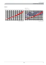
Page 20: ...the charge flow can be increased by 30 to obtain a lower ΔT The diagrams show the heat pump with a high fan speed at low fan speeds ΔT will be 0 5 to 1 degrees lower does not apply to F2015 6 kW which only has one fan speed 1 flow temperature 35 2 flow temperature 45 3 flow temperature 55 F2015 6 2 3 4 5 6 7 8 9 10 11 12 15 10 5 0 5 10 15 20 25 30 1 2 3 1 2 3 2 4 6 8 10 12 14 16 18 20 22 15 10 5 0...

Page 21: ... 1 2 3 3 2 1 5 10 15 20 25 30 4 6 8 10 12 14 16 18 20 15 10 5 0 5 10 15 20 25 30 1 2 3 ΔT Phase current A Specified output kW Outdoor temperature Outdoor temperature Rated output Phase current 19 F2015 For the Installer Commissioning and adjusting ...

Page 22: ...ff H0 Drip tray heater off C1 F2 H2 S1 01 Compressor on circulation pump on C1 Fan on high speed F2 Compressor heater off H2 Drip tray heater on CD F0 H2 S1 02 Defrosting in progress CD CC F0 H3 S1 01 Compressor off circulation pump on CC Compressor heater on H3 Drip tray heater on Heater H0 The compressor heater is always active when the compressor is switched off The drip tray heater is connecte...

Page 23: ... out has tripped 07 Sensor alarm One of the temperature sensors is defective 08 Communication error only when SMO 10 VVM300 is connected 09 High pressure pressostat has tripped during defrost ing resets automatically 10 Not used 11 Flow and return line sensors fitted incorrectly 12 Hot outdoor air Appears when the outdoor air heater temperature exceeds 35 C 13 High flow temperature 14 Defrosting i...

Page 24: ...e is adjustable between 20 and 60 minutes Factory setting 20 minutes A4 Balance temperature the set outdoor air temperature when the additional relay 14 can be activated from channel A6 without affecting compressor operations Additional heat relay 14 is activated first after the set time on channel A6 The value can be set between 15 set stop temperature channel A7 and 10 C Factory setting is 0 C A...

Page 25: ...er has counted to 60 minutes The com pressor is permitted to start again utelufttemp A B 1 2 3 4 5 6 Utelufttemperatur 2XWGRRU WHPSHUDWXUH Tip It is heat pump s outdoor sensor that applies If VVM 300 SMO 10 is connected it is not the value in menu 4 0 but the value in the outdoor air temperature in menu 5 9 which is used Control conditions defrosting ႑ A time counter counts up every minute if the ...

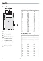
Page 26: ...51 35 4 60 53 44 30 4 47 39 29 25 4 31 29 20 20 4 12 21 93 15 3 90 16 62 10 3 65 12 71 5 3 38 9 81 0 3 09 7 62 5 2 80 5 97 10 2 50 4 71 15 2 22 3 75 20 1 95 3 00 25 1 70 2 42 30 1 47 1 96 35 1 27 1 60 40 1 09 1 31 45 0 94 1 08 50 0 70 0 746 60 0 51 0 525 70 Data for discharge sensor Voltage V Resistance k Temperature C 1 27 1 71 40 1 12 1 44 45 0 97 1 21 50 0 88 1 07 55 0 74 0 87 60 0 64 0 74 65 0...

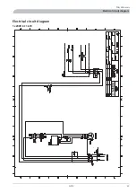
Page 27: ...Electrical circuit diagram 1x230V 6 11 kW 25 F2015 Miscellaneous Electrical circuit diagram ...

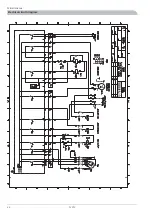
Page 28: ...F2015 26 Miscellaneous Electrical circuit diagram ...

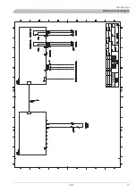
Page 29: ...27 F2015 Miscellaneous Electrical circuit diagram ...

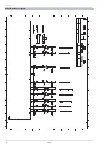
Page 30: ...F2015 28 Miscellaneous Electrical circuit diagram ...

Page 31: ...Technical specifications Component positions LEK LEK 29 F2015 Miscellaneous Technical specifications ...

Page 32: ...set button 40 Low pressure pressostat 41 Service connection high pressure 42 Display contrast 43 Connection communications 44 Expansion valve 48 Operating condenser fan 57 Capacitor 61 Particle filter supplied 63 Drying filter 65 Non return valve 66 Contactor compressor 68 Connection heating medium out of F2015 G1 Ø28 mm 70 Connection heating medium in to F2015 G1 Ø28 mm 71 Temperature sensor evap...

Page 33: ...ected by walls bricks differences in ground level etc and should therefore only be seen as guide values F2015 works with low fan speed or high fan speed depend ing on the outdoor temperature R LEK 1 m 4 m 10 m F2015 11 F2015 8 F2015 6 57 62 57 62 57 LW A Sound power level 51 56 51 56 51 dB A Sound pressure level at 1 m Fan low high 39 44 39 44 39 dB A Sound pressure level at 4 m Fan low high 31 36...

Page 34: ...5 1200 30 50 200 130 520 70 71 350 mm 400 mm 3 m Fritt utrymme bakom Fritt utrymme framför Fritt utrymme Min avstånd vid användning av flera F 2025 UHH VSDFH UHH VSDFH EHKLQG UHH VSDFH LQ IURQW 0LQ GLVWDQFH ZKHQ XVLQJ VHYHUDO F2015 32 Miscellaneous Technical specifications ...

Page 35: ...50Hz Operating voltage Scroll compressor Compressor 0 25 0 20 0 16 l s Nominal flow heating medium 2 2 1 5 1 3 kPa Internal pressure drop at nominal flow 0 5 2 5 bar Min max pressure heating medium side 1700 2000 1700 2000 1500 m3 h Airflow 90 130 90 130 70 W Nominal output fan 25 20 20 A Fuse IP 24 Enclosure class 60 C Max outgoing heating medium temperature 2 1 2 1 1 9 kg Refrigerant volume R407...

Page 36: ...5 0 5 10 15 20 25 30 35 40 DWHU WHPSHUDWXUH r r 2XWGRRU DLU WHPSHUDWXUH 6XSSO WHPSHUDWXUH 5HWXUQ WHPS During shorter time it is allowed to have lower working temperatures on the water side e g during start up F2015 34 Miscellaneous Technical specifications ...

Page 37: ...450 300 Part No 088 660 L E K 10 15 20 25 30 C LE K LE K RT 10 HR 10 KVT 10 Room thermostat Auxiliary relay Condensation water trough Part no 418 366 Part no 089 423 Part no 089 686 AJ LEK VT 10 VST 20 VST 11 Heating thermostat Hot water control Hot water control Part no 418 801 Three way valve DN 32 11 4 Shuttle valve Cu pipe Ø28 Max recommended charge power 40 kW Max recommended charge power 15 ...

Page 38: ...ed high pressure pressostat Indicated as 06 in channel S1 Cause Check that the system has been vented correctly Check the fuses Check that the particle filter is not blocked Check that the circulation pump is rotating If the fault remains contact the installa tion engineer Action Tripped low pressure pressostat Indicated as 05 in channel S1 Cause Ensure that the air flow is not blocked If the faul...

Page 39: ...1 in any SMO 10 Check the charge flow and the particle filter which may be partially clogged Action Fan stopped Cause Ensure that the air flow is not blocked If the fault remains contact the installation engineer Action The alarm is acknowledged by the voltage to the heat pump being interrupted and then restarted Draining heat medium side In the event of prolonged power failures it is recommended ...

Page 40: ...F2015 38 ...

Page 41: ...39 F2015 ...

Page 42: ...F2015 40 ...

Page 43: ......

Page 44: ... dk www volundvt dk NIBE Systemtechnik GmbH Am Reiherpfahl 3 29223 Celle Tel 05141 7546 0 Fax 05141 7546 99 E mail info nibe de www nibe de Druzstevni zavody Drazice s r o Drazice 69 CZ 294 71 Benatky nad Jizerou Tel 420 326 373 801 Fax 420 326 373 803 E mail nibe nibe cz www nibe cz CH NIBE Wärmetechnik AG Winterthurerstrasse 710 CH 8247 Flurlingen Tel 52 647 00 30 Fax 52 647 00 31 E mail info ni...

Reviews: