For Home Owners
General
System description
Principle of operation
3
Maintenance routines
General
4
For the Installer
General points for the installation engineer
Transport and storage
5
Inspection of the installation
5
Assembly
5
Control
5
Pipe connections
General
6
Pipe coupling heating medium circuit
6
Water volumes
6
Pressure drop, heating medium side
6
Docking
General
7
Abbreviations
7
F2015 docked with VVM 300 (fixed condensing)
7
F2015 docked to the oil-fired/pellet boiler together with SMO
10 and water heater (floating condensing)
8
Several F2015 together with SMO 10 and water heater (floating
condensing)
9
F2015 docked to an electric/oil boiler (floating condens-
ing)
10
F2015 docked with wood fired boiler and hot water heater
(fixed condensing)
11
Electrical connections
General
13
Connection
13
Charge pump
14
Anti-freeze function
14
External heat cable
14
Outside sensor
14
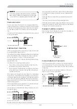
Thermostat control
15
Additional heat / Downtime
15
Example of addition connection
15
External indication of main alarm
15
Commissioning and adjusting
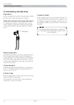
Preparations
16
Filling and venting the heating medium system
16
Balance temperature
16
Stop temperature
16
Soft-start relay
16
Compressor heater
16
Start-up and inspection
17
Readjusting, heating medium side
17
Adjustment, charge flow
18
Control
Explanation
20
Channel descriptions
21
Control conditions, cold outdoor air
23
Control conditions defrosting
23
Sensor placement
Temperature sensor data
24
Data for discharge sensor
24
Miscellaneous
Electrical circuit diagram
1x230V 6-11 kW
25
Technical specifications
Component positions
29
Sound pressure levels
31
Dimensions and setting-out coordinates
32
Technical specifications
33
Enclosed kit
35
Accessories
35
Dealing with malfunctions
Checking the status
36
F2015 is not operational
36
Draining, heat medium side
37
1
F2015
Table of Contents
Summary of Contents for F2015
Page 1: ...INSTALLATION AND MAINTENANCE INSTRUCTIONS MOS GB 1008 3 F2015 031239 F2015 LEK ...
Page 2: ......
Page 27: ...Electrical circuit diagram 1x230V 6 11 kW 25 F2015 Miscellaneous Electrical circuit diagram ...
Page 28: ...F2015 26 Miscellaneous Electrical circuit diagram ...
Page 29: ...27 F2015 Miscellaneous Electrical circuit diagram ...
Page 30: ...F2015 28 Miscellaneous Electrical circuit diagram ...
Page 40: ...F2015 38 ...
Page 41: ...39 F2015 ...
Page 42: ...F2015 40 ...
Page 43: ......


