Pipe connections
General
Pipe installation must be carried out in accordance with cur-
rent norms and directives.
F2015 operates up to a return temperature of about 50 °C
and an outgoing temperature of about 58 °C from the heat
pump. Because F2015 is not equipped with shut off valves
these must be installed outside the heat pump to facilitate
any future servicing. The return temperature is limited by the
return line sensor and is adjusted on channel A2.
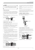
NOTE
The pipe work must be flushed before the heat pump
is connected, so that any contaminants do not damage
the components parts.
Pipe coupling heating medium circuit
F2015 can be connected to the heating system, see the
"Docking" section or one of the system solutions that can
be downloaded from the website www.nibe.eu.
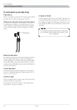
The heat pump must be vented by the upper connection (70,
HM-out) using the venting nipple on the enclosed flexible
hose.
The supplied particle filter (SF) must be installed before the
inlet, i.e. the lower connection (71, HM-in) on F2015.
All
outdoor pipes must be thermally insulated with at least
19 mm thick pipe insulation.
The charge pump must be operational, even if F2015
is not running, to prevent damage due to freezing.
The charge pump can also be controlled directly from F2015,
terminal block (11), which takes the outdoor temperature
into consideration. Alternatively, the heat pump is connected
to an intermediate circuit with a heat exchanger, pump and
water with anti-freeze.
Shutoff (AV) and drain valves (TV) are fitted so that F2015
can be emptied in the event of prolonged power failures.
The supplied flexible hoses act as vibration dampers. The
flexible hoses are fitted so a slight bend is created, thus acting
as vibration damping.
Water volumes
When docking with F2015, a total water volume, in the
boiler and accumulator, of at least 20 litres boiler water per
kW output on the heat pump is recommended.
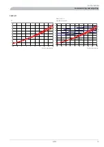
Pressure drop, heating medium side
F2015 -6, 8, 11
0
1
2
3
4
5
6
7
8
9
0
0,10
0,20
0,30
0,40
0,50
0,60
0,70
kPa
Tryckfall
6 kW
8, 11 kW
Flöde
l/s
3UHVVXUH GURS
)ORZ
OV
N3D
L
+HDW LQVXODWLRQ
F2015
6
For the Installer
Pipe connections
Summary of Contents for F2015
Page 1: ...INSTALLATION AND MAINTENANCE INSTRUCTIONS MOS GB 1008 3 F2015 031239 F2015 LEK ...
Page 2: ......
Page 27: ...Electrical circuit diagram 1x230V 6 11 kW 25 F2015 Miscellaneous Electrical circuit diagram ...
Page 28: ...F2015 26 Miscellaneous Electrical circuit diagram ...
Page 29: ...27 F2015 Miscellaneous Electrical circuit diagram ...
Page 30: ...F2015 28 Miscellaneous Electrical circuit diagram ...
Page 40: ...F2015 38 ...
Page 41: ...39 F2015 ...
Page 42: ...F2015 40 ...
Page 43: ......


