background image


Section-2


www.newavenergy.com


 04-1206_S2_NW_OPMPS_10-50kVA_GB_110201.doc 

Page  14/14 

Printed in Switzerland – Modifications reserved


This page left intentionally blank 


Summary of Contents for PowerScale

Page 1: ...ng the entire life cycle TCO Low input harmonic distortion Cost saving during installation Input Power Factor near unity Cost savings during installation and the entire life cycle TCO Compact size Flo...

Page 2: ...a a SA Arturo Soria 329 1 D ES 28033 Madrid Tel 34 91 768 22 22 Fax 34 91 383 21 50 newave newave es www newave es Switzerland Newave Energy AG Industriestrasse 5 CH 5432 Neuenhof Switzerland Tel 41 5...

Page 3: ...2 1 MECHANICAL CHARACTERISTICS POWERSCALE 10 15KVA CABINET A 1 2 2 MECHANICAL CHARACTERISTICS POWERSCALE 10 25KVA CABINET B 1 2 3 MECHANICAL CHARACTERISTICS POWERSCALE 30 50KVA CABINET C 1 2 4 GENERAL...

Page 4: ...S 232 SUB D9 FEMALE AND USB PORT 3 1 2 CUSTOMER INTERFACE AND DRY PORTS TERMINALS X1 STANDARD 3 1 3 JR1 RS485 INTERFACE FOR MULTIDROP 4 SECTION 4 4 1 OPERATION 4 1 1 COMMISSIONING 4 1 2 CONTROL PANEL...

Page 5: ...ECHNICAL CHARACTERISTICS 10 2 1 MECHANICAL CHARACTERISTICS POWERSCALE 10 15KVA CABINET A 10 2 2 MECHANICAL CHARACTERISTICS POWERSCALE 10 25KVA CABINET B 10 2 3 MECHANICAL CHARACTERISTICS POWERSCALE 30...

Page 6: ...0 10 BATTERY AUTONOMIES 10 10 1 EXAMPLES OF BATTERY AUTONOMY AT FULL LOAD WITH STANDARD CABINETS AND STANDARD BATTERY CONFIGURATION 10 11 INSTALLATION PLANNING 10 11 1 HEAT DISSIPATION PER UPS RANGE W...

Page 7: ...be done by the manufacturer s qualified technicians or their authorized service partners OPERATIONS INSIDE THE UPS MUST BE PERFORMED BY A SERVICE ENGINEER FROM THE MANUFACTURER OR FROM AN AGENT AUTHO...

Page 8: ...e enhanced power performance parallel capability and connectivity s interaction When operating in parallel configuration each POWERSCALE can take the leadership role avoiding single points of failure...

Page 9: ...ible Battery Management FBM 7 1 2 4 3 Feature DPA Technology Decentralized Parallel Architecture 7 1 2 5 QUALITY STANDARDS AND UPS CLASSIFICATION CODE 7 1 2 6 SINGLE PARALLEL CONFIGURATIONS 8 1 2 7 WA...

Page 10: ...y other connection to the equipment A terminal to which or from which a direct current or voltage may be applied or supplied Three phase alternating current This symbol indicates the word phase ON The...

Page 11: ...in these measures the operator of the USP System must adhere to the instructions in this manual Any deviations from the instructions could be dangerous to the user or cause accidental load loss NEWAV...

Page 12: ...F Maximum Relative Humidity 95 non condensing The UPS cabinet uses forced air cooling to regulate internal component temperature Air inlets are in the bottom sides and front of the cabinet and outlets...

Page 13: ...ine power failures 1 2 1 MECHANICAL CHARACTERISTICS POWERSCALE 10 20KVA CABINET A PowerScale Cabinet A Power range kVA 10 15 20 Dimensions WxHxD mm 345x720x710 Weight without battery kg 60 62 64 Weigh...

Page 14: ...sensitive electronic equipment requires for reliable operation During brownouts blackouts and other power interruptions batteries provide emergency power to safeguard operation The UPS system is house...

Page 15: ...ralized Parallel Architecture The UPS product features DPA paralleling technology that provides N X redundancy without introducing a single point of failure The products utilizing the DPA technology a...

Page 16: ...d subsidiaries or distributors The warranty does not apply in any case of damage or loss caused by misuse negligence unauthorized repair or modification incorrect installation and commissioning inappr...

Page 17: ...o not drop the equipment Do not either stack the pallets because of high energy batteries involved and the heavy weight NOTE IF THE UPS IS NOT IMMEDIATELY INSTALLED THE FOLLOWING GUIDELINES MUST BE FO...

Page 18: ...ESTIGATION 1 3 3 UNPACKING Unpack the equipment by removing the packing and shipping materials Make a visual inspection and check that Tip Tel indicator FRAGILE and ARROW on the packing container is i...

Page 19: ...ly be connected when the UPS is commissioned The battery life depends very much on the ambient temperature A temperature range between 18 and 23 C will achieve the optimum battery life If the UPS is d...

Page 20: ...om the front and rear making it a service friendly and maintenance friendly UPS Reserve enough space from the front min 900 mm The UPS should be located where Humidity 90 non condensing and temperatur...

Page 21: ...BETWEEN THE UPS AND THE EXTERNAL BATTERY CABINET S THE BATTERY CABINET IS CONNECTED ELECTRICALLY IN PARALLEL WITH THE INTERNAL BATTERIES OF THE UPS WARNING IF AVAILABLE THE INTERNAL BATTERY HAS TO BE...

Page 22: ...YOU RUN RISK OF EXPOSURE TO DANGEROUS VOLTAGES PHYSICAL INJURY OR DEATH MAY FOLLOW OR DAMAGE MAY OCCUR TO THE UPS OR THE LOAD EQUIPMENT IF THESE INSTRUCTIONS ARE IGNORED To ensure correct operation of...

Page 23: ...ide additional protection to the UPS in the event of overloads and short circuits 1 5 1 1 Mains Supply and Earth connection To ensure protection of personnel during the installation of UPS make sure t...

Page 24: ...nput feed it is possible to use both terminals mains or bypass For minimum recommended Input Cable Sections and Fuse Ratings Section 2 chapter 2 1 3 Under the connection terminal of the UPS there is a...

Page 25: ...MAINS INPUT CABLE UPS TERMINAL Rectifier BYPASS INPUT CABLE UPS TERMINAL Bypass Phase L1 1L1 Phase L1 2L1 Phase L2 1L2 Phase L2 2L2 Phase L3 1L3 Phase L3 2L3 NEUTRAL 1N NEUTRAL 2N EARTH PE EARTH PE F...

Page 26: ...n distribution board is used sockets for Mains and UPS voltage ensure that on each socket there is an indication of the applied voltage Mains or UPS Output power cable ratings should be in accordance...

Page 27: ...ery cabinet installation instructions have been completed Air conditioning equipment is installed and operating properly The area around the installed UPS system is clean and dust free It is recommend...

Page 28: ...Section 1 www newavenergy com 04 1206_S1_NW_OPMPS_10 50kVA_GB_110201 doc Page 20 20 Printed in Switzerland Modifications reserved This page left intentionally blank...

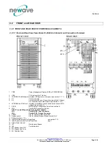
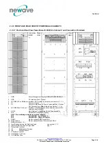
Page 29: ...le 10 20kVA in Cabinet A and Connection Terminals 4 2 2 2 FRONT AND REAR VIEW OF POWERSCALE CABINET B 5 2 2 2 1 Front and Rear View PowerScale 10 25kVA in Cabinet B and Connection Terminals 5 2 2 3 FR...

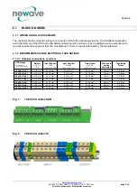
Page 30: ...rview UPS Range Terminals T Connection Bar B Battery N PE Input Bypass 3 N N 2L1 2L2 2L3 Input Rectifier 3 N PE N 1L1 1L2 1L3 Output load 3 N PE N 3L1 3L2 3L3 Max cable section admissible Toghtening T...

Page 31: ...E VERSION ON REQUEST DUAL INPUT FEED Power kVA Fuse B Agl CB Cable B IEC 60950 1 2001 Fuse C Agl CB Cable C IEC 60950 1 2001 Cable D IEC 60950 1 2001 Fuse E N Cable E N 10 3x20 5x2 5 3x20 4x2 5 5x2 5...

Page 32: ...s detail see Section 3 1 2 6 JR1 RS485 on RJ 45 port Interface for Multidrop connection between several UPS cabinets see Section 3 7 SW1 9 Multi Cabinet Configuration Switch see section 4 8 JD8 Parall...

Page 33: ...e Section 3 1 2 6 JR1 RS485 on RJ 45 port Interface for Multidrop connection between several UPS cabinets see Section 3 7 SW1 9 Multi Cabinet Configuration Switch see section 4 8 JD8 Parallel BUS conn...

Page 34: ...port Interface for Multidrop connection between several UPS cabinets see Section 3 7 SW1 9 Multi Cabinet Configuration Switch see section 4 8 JD8 Parallel BUS connector Option ONLY For paralleling ca...

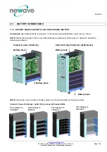
Page 35: ...enclosures are shown NOTE Within the cabinets A B in only 7 9Ah batteries are allowed 16 48 blocks in Cabinet C also 28Ah batteries are allowed Cabinet A max 48 blocks Cabinet B max 96 blocks 2x48 blo...

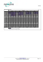
Page 36: ...ax 1 x 48 x 7 9Ah batteries Cabinet B max 2 x 48 x 7 9Ah batteries 20 blocs 22 blocs 24 blocs 20 blocs 22 blocs 24 blocs 6kW 8kW 9kW Powerscale 10kVA 9kW Load Power Autonomy min 7Ah batt 9Ah batt 7Ah...

Page 37: ...2 x 38 1 x 48 2 x 48 2 x 40 2 x 48 10 2 x 34 1 x 48 2 x 46 2 x 32 3 x 40 2 x 40 3 x 46 2 x 46 12 2 x 40 2 x 28 2 x 48 2 x 36 3 x 44 2 x 44 3 x 48 2 x 48 13 3 x 48 2 x 48 n a 15 2 x 48 2 x 32 1 x 24 3...

Page 38: ...W 16 blocs 20 blocs 24 blocs 28 blocs Powerscale 30kVA 27kW Load Power Autonomy min 7Ah batt 9Ah batt 28Ah batt 7Ah batt 9Ah batt 28Ah batt 7Ah batt 9Ah batt 28Ah batt 7Ah batt 9Ah batt 28Ah batt 6 2...

Page 39: ...n a n a n a n a n a n a 20 n a n a n a n a n a n a n a n a n a n a n a n a 22 n a n a n a n a n a n a n a n a n a n a n a n a 24 n a n a n a n a n a n a n a n a n a n a n a n a 25 n a n a n a n a n a...

Page 40: ...nsure protection of the personnel during the installation of the UPS make sure that the connections are performed under the following conditions No mains voltage is present in the UPS All the loads ar...

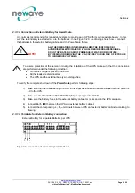
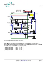
Page 41: ...xternal battery If the UPS has to be configured with external batteries the internal battery link to the position of F1 Battery Fuse has to be replaced by the short Links delivered separately at the b...

Page 42: ...Section 2 www newavenergy com 04 1206_S2_NW_OPMPS_10 50kVA_GB_110201 doc Page 14 14 Printed in Switzerland Modifications reserved This page left intentionally blank...

Page 43: ...eserved SECTION 3 3 1 INTERFACING 2 3 1 1 SMART PORT JD1 SERIAL RS 232 SUB D9 FEMALE AND USB PORT 2 3 1 2 CUSTOMER INTERFACE AND DRY PORTS TERMINALS X1 STANDARD 3 3 1 2 1 Input Interfaces Terminal blo...

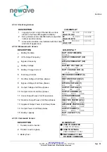
Page 44: ...mote signalling and automatic computer shutdown SNMP Card slot already included SNMP card For monitoring and integration in network management 3 1 1 SMART PORT JD1 SERIAL RS 232 SUB D9 FEMALE AND USB...

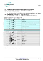
Page 45: ...12 Vdc source X1 9 IN 12Vdc Max 200mA load X1 8 GND GND Remote Shut down X1 7 IN 12Vdc Do not remove the factory mounted bridge until an external remote shut down is connected X1 6 GND GND Temperature...

Page 46: ...t 2 Slot 1 Cabinet A B Slot 2 Slot 1 1 PMD Power Management Display PMD of POWERSCALE 2 USB PC Interface Slot 1 Option 3 JD1 RS232 Sub D9 female Interface UPS system to computer see section 3 1 1 4 X1...

Page 47: ...s 3 4 1 2 3 Keys 3 4 1 2 4 ON OFF Start up and Shutdown Buttons 3 4 1 3 DESCRIPTION OF THE LCD 4 4 1 3 1 Status Screens 4 4 1 3 2 Main Menu Screen 4 4 1 3 3 Event Log Screen 5 4 1 3 4 Measurements Scr...

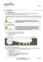
Page 48: ...TURER 4 1 2 CONTROL PANEL WARNING ONLY PERSONS WHICH HAVE BEEN TRAINED BY SERVICE TECHNICIANS OF THE MANUFACTURER OR HIS AUTHORIZED SERVICE PARTNERS ARE ALLOWED TO OPERATE ON THE CONTROL PANEL WITH CL...

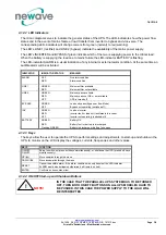
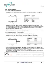
Page 49: ...EEN RED OFF Mains bypass available Mains bypass not OK or not available UPS is turned off BY PASS GREEN OFF Load on bypass Bypass or Eco Mode Bypass not operating switched off INV GREEN RED OFF Load o...

Page 50: ...by the UPS number The max no of module units are 2 per system EXEMPLES S stands for Single UPS The system consists of ONLY one UPS P1 stands for Parallel UPS in a Multi UPS system and 01 stands for t...

Page 51: ...00 00 00 00 00 00 11 Active Output Power of all three phases ACTIVE POWER KW 00 00 00 00 00 00 12 Reactive Output Power of all three phases REACTIVE POWER kVAr 00 00 00 00 00 00 13 Apparent Output Pow...

Page 52: ...LCD DISPLAY 1 Set up Language not active yet SET LANGUAGE SET DATE AND TIME ENGLISH FRANCAIS POLISH 2 Set up Date and Time SET UP DATE TIME SET UP BATT TEST DD MM YY HH MM SS 3 Set up battery test SE...

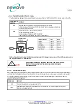
Page 53: ...ruption to the static bypass mains supply transfer time 0 4 1 4 2 Mode OFF LINE ECO or BYPASS MODE In the OFF Line Mode the load is supplied from the mains through the static bypass Using the control...

Page 54: ...F INVERTER RED Green BATTERY Green Green Before transferring the load to Maintenance Bypass IA1 always make sure all the UPS modules are in the Bypass Mode or ECO Mode NOTE ON OPERATION MODE MANUAL BY...

Page 55: ...Printed in Switzerland Modifications reserved CONTENTS SECTION 5 5 1 OPERATION PROCEDURES 2 5 1 1 START UP PROCEDURE 2 5 1 2 SHUTDOWN PROCEDURE 4 5 1 3 LOAD TRANSFER FROM INVERTER OPERATION TO MAINTEN...

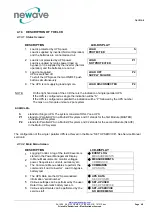
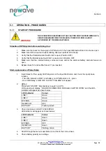
Page 56: ...l battery enclosure fuses and or the external battery cabinets fuses are open 6 Bypass fuses F2 and rectifier fuses F1 are inserted Start up procedure of PowerScale 1 Insert fuses for the supply of UP...

Page 57: ...N On output Terminal Block there is now UPS power and on all LCD s LOAD PROTECTED will appear now the two units are operating in parallel 13 Perform step 11 and 12 until all the unit of the system are...

Page 58: ...n be completely shutdown The following procedures can only be executed after the load has completely been de energized NOTE IN THE CASE THAT THE PARALLEL UPS SYSTEM HAS TO BE TURNED OFF THEN BOTH ON O...

Page 59: ...S and transfer the load to mains for parallel operation is enough to give the order in one of the units On LCD panel LOAD NOT PROTECTED will appear 2 Close Maintenance Bypass Switch IA1 position ON fo...

Page 60: ...s LOAD OFF SUPPLY FAILURE will appear and the mimic panel will show LED Indicator Colour LINE 1 Green LINE 2 OFF BYPASS OFF INVERTER OFF BATTERY Flashing Green 3 Close all Parallel Isolators IA2 and...

Page 61: ...ction of Parallel Communication Cables BUS lines 3 6 1 2 2 2 Parallel Adapter and DIP Switch SW2 2 4 6 1 2 3 DIP Switch SW1 9 Settings 4 6 1 2 4 DIP Switch SW1 9 4 6 1 2 5 ON OFF Main Buttons 5 6 1 2...

Page 62: ...h off Every UPS unit in a parallel configuration is provided with a proper output parallel Isolator IA2 which when opened isolates the corresponding unit from the parallel system Once the parallel iso...

Page 63: ...h single UPS it is necessary to connect the units together to form the parallel system For this purpose a communication BUS line is connected sequentially between the units Connect communication BUS l...

Page 64: ...rrect positions 6 1 2 4 DIP Switch SW1 9 The DIP Switch SW1 9 is located on every Cabinet POWERSCALE With this switch it is possible to determine the position of an POWERSCALE Cabinet in a Multi Cabin...

Page 65: ...IT ON WHICH ISOLATOR IA2 IS BEING CLOSED IS ALSO ON INVERTER 6 1 2 7 Maintenance Bypass IA1 There are two types of Parallel System Configurations redundant and capacity parallel systems see SECTION 5...

Page 66: ...CALE Cabinets been set correctly according to Paragraphs 6 1 2 2 2 and 6 1 2 4 4 All the internal if any and or external battery cabinets racks have been connected correctly The start up of a parallel...

Page 67: ...01 doc Page 1 4 Printed in Switzerland Modifications reserved CONTENTS SECTION 7 7 1 MAINTENANCE 2 7 1 1 INTRODUCTION 2 7 1 2 USER RESPONSIBILITIES 2 7 1 3 ROUTINE MAINTENANCE 2 7 1 4 BATTERY TEST 2 7...

Page 68: ...reliability of the UPS are maximized When the UPS is commissioned the commissioning field service engineer will attach a service record book to the front of the UPS and this will be used to record th...

Page 69: ...e battery maintenance shall be performed by a service engineer from the manufacturer or from an agent authorized by the manufacturer 7 1 6 BATTERY DISPOSAL AND RECYCLING Batteries contain dangerous su...

Page 70: ...Section 7 www newavenergy com 04 1206_S7_NW_OPMPS_10 50kVA_GB_110201 doc Page 4 4 Printed in Switzerland Modifications reserved This page left intentionally blank...

Page 71: ..._NW_OPMPS_10 50kVA_GB_110201 doc Page 1 2 Printed in Switzerland Modifications reserved CONTENTS SECTION 8 8 1 TROUBLESHOOTING 2 8 1 1 ALARMS 2 8 1 2 MENU COMMANDS EVENT LOG AND MEASUREMENTS 2 8 1 3 F...

Page 72: ...input power to UPS is too low or missing If site power appears to be OK check the input circuit breakers etc supplying the UPS OUTPUT SHORT There is a short circuit at the output of UPS on load side...

Page 73: ...TIONS 2 9 1 1 INTRODUCTION 2 9 1 2 REMOTE SHUT DOWN 2 9 1 3 GENERATOR ON FACILITIES 3 9 1 4 WAVEMON SHUTDOWN AND MANAGEMENTSOFTWARE 3 9 1 4 1 Why is UPS Management important 3 9 1 4 2 WAVEMON Shutdown...

Page 74: ...down procedure is disabled and it should be activated by a Hardware Code on Setup Service menu Please contact your distributor to enable this operation The remote shutdown on terminal port X1 7 X1 8 i...

Page 75: ...low state In the event of a power disturbance system administrators can also monitor their network from a central location allowing an early detection of problems In fact utility power is unreliable a...

Page 76: ...rv collects messages received from the UPS The UPSServ interprets received messages and makes them available to the client module UPSCli and to any SNMP based management station When UPSServ detects v...

Page 77: ...P CARD ADAPTER FOR NETWORK MANAGEMENT REMOTE MONITORING The Simple Network Management Protocol SNMP is a worldwide standardized communication protocol It is used to monitor any device in the network v...

Page 78: ...network The new release RCCMD2 is an application available for all Operating Systems analogous to PMC Software Our SNMP Interfaces are compatible to RCCMD 9 1 6 MODEM ETHERNET CARD NEWAVEWATCH MANAGE...

Page 79: ...alysis and diagnostics report Visualization of the UPS data Current status single and parallel operation Measured values for single or three phase Recording function including graphs with zooming capa...

Page 80: ...Section 9 www newavenergy com 04 1206_S9_NW_OPMPS_10 50kVA_GB_110201 doc Page 8 8 Printed in Switzerland Modifications reserved This page left intentionally blank...

Page 81: ...e life cycle TCO Low input harmonic distortion Cost saving during installation Input Power Factor near unity Cost savings during installation and the entire life cycle TCO Compact size Floor space cos...

Page 82: ...C EFFICIENCY with Linear load up to cos 1 8 10 6 ENVIRONMENTAL CHARACTERISTICS 9 10 7 STANDARDS 9 10 8 COMMUNICATION 10 10 8 1 POWER MANAGEMENT DISPLAY PMD 10 10 8 2 MIMIC DIAGRAM 10 10 8 3 DISPLAY 10...

Page 83: ...e enhanced power performance parallel capability and connectivity s interaction When operating in parallel configuration each POWERSCALE can take the leadership role avoiding single points of failure...

Page 84: ...WxHxD mm 345x720x710 Weight without battery kg 60 62 64 Weight with battery with 48 block of 7Ah kg 180 182 184 with standard packaging kg 4 Colour Graphite grey RAL 7024 10 2 2 MECHANICAL CHARACTERIS...

Page 85: ...40 50 Nominal Input Voltage V 3x380 220V N 3x400V 230V N 3x415 240V N Input Voltage Tolerance ref to 3x400 230V for Loads in V 23 15 3x308 177 V to 3x460 264 V for 100 load 30 15 3x280 161 V to 3x460...

Page 86: ...ved 10 3 1 GRAPH INPUT PF VERSUS LOAD Input Power factor Leading 0 96 0 985 0 99 0 99 0 0 2 0 4 0 6 0 8 1 25 50 75 100 Load Input Power Factor 10 3 2 GRAPH INPUT DISTORTION THDi VERSUS LOAD Input Curr...

Page 87: ...ies is 50 Description Cabinet Type Maximum Power in kW 6 8 9 6 8 9 8 10 12 13 5 8 10 12 13 5 9 12 16 18 9 12 16 18 12 16 20 22 5 Minimum number of battery blocks per String 20 22 24 16 22 24 22 28 32...

Page 88: ...Load 2 With Non linear Load EN62040 3 2001 4 Output Frequency Hz 50 Hz or 60 Hz Output Frequency Tolerance Synchronized with mains 2 selectable for bypass operation or 4 Free running 0 1 Bypass opera...

Page 89: ...ng Factor for Power 1500 4850 0 95 2000 6600 0 91 2500 8250 0 86 De rating factor for use at altitudes above 1000m sea level according IEC 62040 3 3000 9900 0 82 Relative Air humidity Max 95 non conde...

Page 90: ...10 8 2 MIMIC DIAGRAM The mimic diagram serves to give the general status of the UPS The LED indicators show the power flow status and in the event of mains failure or load transfer from inverter to b...

Page 91: ...unction X1 10 GND GND 12 Vdc source X1 9 IN 12Vdc Max 200mA load X1 8 GND GND Remote Shut down X1 7 IN 12Vdc Do not remove the factory mounted bridge until an external remote shut down is connected X1...

Page 92: ...zed communication protocol It is used to monitor any device in the network via simple control language The UPS Management Software WaveMon also provides its data in this SNMP format with its internal...

Page 93: ...abinet A max 1 x 48 x 7 9Ah batteries Cabinet B max 2 x 48 x 7 9Ah batteries 20 blocs 22 blocs 24 blocs 20 blocs 22 blocs 24 blocs 6kW 8kW 9kW Powerscale 10kVA 9kW Load Power Autonomy min 7Ah batt 9Ah...

Page 94: ...2 x 38 1 x 48 2 x 48 2 x 40 2 x 48 10 2 x 34 1 x 48 2 x 46 2 x 32 3 x 40 2 x 40 3 x 46 2 x 46 12 2 x 40 2 x 28 2 x 48 2 x 36 3 x 44 2 x 44 3 x 48 2 x 48 13 3 x 48 2 x 48 n a 15 2 x 48 2 x 32 1 x 24 3...

Page 95: ...kW 16 blocs 20 blocs 24 blocs 28 blocs Powerscale 30kVA 27kW Load Power Autonomy min 7Ah batt 9Ah batt 28Ah batt 7Ah batt 9Ah batt 28Ah batt 7Ah batt 9Ah batt 28Ah batt 7Ah batt 9Ah batt 28Ah batt 6 2...

Page 96: ...n a n a n a n a n a n a 20 n a n a n a n a n a n a n a n a n a n a n a n a 22 n a n a n a n a n a n a n a n a n a n a n a n a 24 n a n a n a n a n a n a n a n a n a n a n a n a 25 n a n a n a n a n a...

Page 97: ...in 200 mm rear space required for fan Input and Output Power Cabling From the bottom on the rear side 10 11 1 HEAT DISSIPATION PER UPS RANGE WITH NON LINEAR LOAD UPS Range 10kVA 15kVA 20kVA 25kVA 30kV...

Page 98: ...TIONS OVERVIEW UPS Range Terminals T Connection Bar B Battery N PE Input Bypass 3 N N 2L1 2L2 2L3 Input Rectifier 3 N PE N 1L1 1L2 1L3 Output load 3 N PE N 3L1 3L2 3L3 Max cable section admissible Tog...

Page 99: ...ERSION ON REQUEST DUAL INPUT FEED Power kVA Fuse B Agl CB Cable B IEC 60950 1 2001 Fuse C Agl CB Cable C IEC 60950 1 2001 Cable D IEC 60950 1 2001 Fuse E N Cable E N 10 3x20 5x2 5 3x20 4x2 5 5x2 5 3x3...

Reviews: