Section-2
www.newavenergy.com
04-1206_S2_NW_OPMPS_10-50kVA_GB_110201.doc
Page 12/14
Printed in Switzerland – Modifications reserved
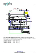
2.3.1.2 Connection of External Battery for PowerScale
It is normally recommended for redundant systems to provide each UPS with its own separate battery. In this
way the redundancy is extended also to the batteries. In the Figure 3.2.3 the drawing shows how to connect
the batteries in the external battery cabinet and the PowerScale frame.
NOTE!
ALL THE OPERATIONS IN THIS MANUAL MUST BE PERFORMED BY
AUTHORISED ELECTRICIANS OR BY QUALIFIED INTERNAL PERSONNEL.
DO NOT OPERATE IN CASE OF PRESENCE OF WATER OR MOISTURE.
BY OPENING OR REMOVING THE UPS-COVERS YOU RUN RISK OF EXPOSURE
TO DANGEROUS VOLTAGES.
To ensure protection of the personnel during the installation of the UPS make sure that the connections
are performed under the following conditions:
•
No mains voltage is present in the UPS
•
All the loads are disconnected
•
The UPS and the external battery are voltage-free
To verify the complete shut down of the
PowerScale
perform following steps:
1) Make sure that the fuses feeding the UPS in the input Distribution Board are all open and no power is
fed to the UPS.
2) Make sure the "MAINTENANCE BYPASS"(IA1) is open (position "OFF”)
3) Make sure the battery fuses in the external battery cabinet or racks and on the UPS are open.
4) Connect
Earth
(PE)
between the UPS and external battery cabinet.
5) Connect
the
corresponding
+ , N,
terminals between UPS and external battery cabinet according to
drawing
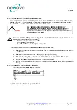
2.3.1.3 Terminals for External Battery connection
External Battery for separate Batteries per UPS
Fig. 3.2.3 Connection of external separate batteries
!
!
+ N -


