background image


10

 
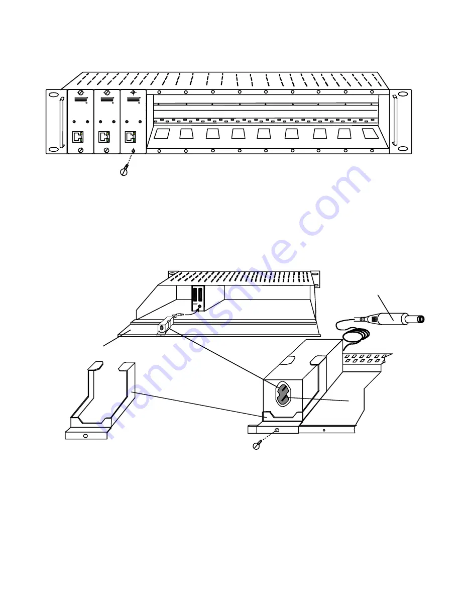
3.   Slide each module into the tray and line up the holes in the mounting plate on the module with corresponding holes in the tray.  
     Secure the module(s) using the two screws provided.  Blank plates and screws are provided to cover empty module spaces.  


                                                                    Figure 10- Secure each module to the tray 


4.  Secure the power supply for each module to the power supply/cable management shelf at the rear of the tray using the bracket  
     and screw supplied.  


                                                      Figure 11- Secure each power supply to the tray 


CAT5

LOCAL UNIT

NTI

R

ST-C5USBVA-300M

XTENDEX

R

USB

CAT5

LOCAL UNIT

NTI

R

ST-C5USBVA-300M

XTENDEX

R

USB

CAT5

LOCAL UNIT

NTI

R

ST-C5USBVA-300M

XTENDEX

R

USB

Secure XTENDEX module(s) to the ST-C5RCK-12
using the screws provided.  

Frontview of ST-C5RCK-12 with XTENDEX Extender Modules

9V

1.5 A

USER

CPU

L
0
C
A
L

U
N

I

T

ST-C 5USB VA- 30 0M

NTI

R

Tel:330- 562- 7070

Fax:330- 562- 1999

1275 Danner Dr

Aurora, OH 44202

   www.networktechinc.com

Secure each power supply to the tray
using the bracket and screw provided.  

Rearview of ST-C5RCK-12 with XTENDEX Extender Modules

Power supply mounting bracket
(supplied with each module)

Connect power cord to
power supply here

Plug power connector
into Extender module

Power supply/cable managment shelf

Summary of Contents for ST-C5USBV-300

Page 1: ...nstallation and Operation Manual XTENDEX Series NETWORK TECHNOLOGIES INCORPORATED Tel 330 562 7070 Fax 330 562 1999 1275 Danner Dr Aurora OH 44202 www networktechinc com NTI R ST C5USBV 300 Desktop Mo...

Page 2: ...5 Danner Drive Aurora Ohio 44202 For more information please contact Network Technologies Inc at 800 742 8324 800 RGB TECH or 330 562 7070 CHANGES The material in this guide is for information only an...

Page 3: ...Figures Figure 1 Connect the Local Unit to a CPU 5 Figure 2 Local unit with audio support connects to CPU 6 Figure 3 Connect local user devices to the Local Unit 6 Figure 4 Connect stereo speakers to...

Page 4: ...on where only these parts are needed without having the CPU there too taking up valuable space and adding to room noise Provides crisp and clear resolution when used in accordance with the chart below...

Page 5: ...ale to Female Extension cable if the Local Unit will be located further than 15 from the CPU or KVM switch CAT5 5e shielded unshielded twisted pair cable s terminated with RJ45 connectors wired straig...

Page 6: ...PU 11 Devices Cable USB Type A male connector for connection to CPU 12 Audio Plug 3 5mm stereo audio plug for connecting to CPU audio line out ST C5USBVA 300 only 13 USER 05 SCSI II Female for connect...

Page 7: ...the Remote and Local Units A properly grounded polarized and preferably surge protected 120V or 240V electrical outlet depending on the AC adapter being used must be installed close enough to the moun...

Page 8: ...the CPU first and then connect the video cable to the adapter Figure 1 Connect the Local Unit to a CPU c If the Local Unit has Audio support ST C5USBVA 300 only connect the black 3 5mm stereo plug in...

Page 9: ...l self powered stereo speakers to the 3 5mm stereo audio jack on the Local Unit See Fig 4 BLUE VIDEO USB CPU BLACK AUDIO 3 5mm Stereo Plug AUDIO CONNECTOR line out ONE WILL BE MARKED line out spkr hea...

Page 10: ...ition the Remote Unit such that the CAT5 cable the monitor cable the keyboard and mouse and the AC adapter power connector can each reach the Remote Unit comfortably 1 Connect the monitor cable to the...

Page 11: ...mote Unit Front View NTI R Network Technologies Inc XTENDEX USB 3 5mm Stereo Audio Jack Stereo Speakers ST C5USBVA 300 Remote Unit VGA Multi Scan Monitor 15HD Female Video Connector CAT5 Cable to Loca...

Page 12: ...X rackmount modules Local and or Remote modules are being installed then an ST C5RCK 12 Rackmount Extender Module Tray must be used sold separately to mount the modules to a RACK The ST C5RCK 12 provi...

Page 13: ...ST C5USBVA 300M XTENDEX R USB CAT5 LOCAL UNIT NTI R ST C5USBVA 300M XTENDEX R USB CAT5 LOCAL UNIT NTI R ST C5USBVA 300M XTENDEX R USB Secure XTENDEX module s to the ST C5RCK 12 using the screws provid...

Page 14: ...ONNECTOR line out ONE WILL BE MARKED line out speaker headphones OR WITH THIS SYMBOL USB Type A male 15HD male Video Connector Connect to ST C5USBVA 300M Local Unit at CPU 0 05 SCSI II series UMTINTA...

Page 15: ...ctor of an Ethernet device Damage to devices connected to the Ethernet may result Figure 14 Connect the CAT5 cable between the Local and Remote Units Green Power LED Yellow CommunicationLED Front View...

Page 16: ...and Local Units see Fig 8 should blink indicating there is proper communication between them Note A loss of signal blank screen may be experienced for an instant during the auto compensation process a...

Page 17: ...l startup the image on the monitor will not be as crisp as the image normally is This is due to the frequency characteristics of the CAT5 cable It may be necessary to enter Command Mode described abov...

Page 18: ...e is ON See Fig 10 3 To reconnect the XTENDEX to a SUN or Windows CPU the default setting press the W key and the MAC LED will go OFF Figure 16 MAC LED After setting the configuration is stored in mem...

Page 19: ...BETWEEN CPU AND MULTI USER MATRIX SWITCH STANDARD APPLICATION BETWEEN USERS AND CPU BETWEEN SINGLE USER KVM SWITCH AND USERS USB Mouse USB Keyboard USB Mouse USB Keyboard USB Keyboard USB Mouse USBVE...

Page 20: ...requency Range 30 Hz to 150 Hz Keyboard Mouse Connectors USB Type A female to local and remote keyboard mouse USB Type A male to CPU Interconnect Cable CAT5 5e Solid UTP STP EIA TIA 568B wiring w male...

Page 21: ...R 3 White Green 3 T 4 Blue 1 R 5 White Blue 1 T 6 Green 3 R 7 White Brown 4 T 8 Brown 4 R Figure 18 Pin positions in female RJ45 connector Note CAT5 connection cable used between NTI XTENDEX Series L...

Page 22: ...t Windows Logo Command Meta SB R Arrow SB R Arrow Power Suspend SB Space Bar L and R Left and Right keys when two keys are marked the same on a keyboard SUN s 16 Extra Keys Use the chart below to type...

Page 23: ...e Break Print Screen SysRq Application Key Windows Logo Key Windows Logo Key Enter Return Alt Graph Shift Shift Control Tab Capslock Alt Backspace Num Lock Help Stop Props Front Open Find Cut Paste Co...

Page 24: ...ify length is within specified limits 300 Check cable connections Make sure they are snapped in properly and completely See pg 10 for instruction on Video Quality Adjustment Monitor sometimes loses sy...

Page 25: ...two 2 years from the date of purchase Please contact Network Technologies Inc at 800 742 8324 800 RGB TECH or 330 562 7070 or visit our website at http www networktechinc com for information regardin...

Reviews: