background image

4

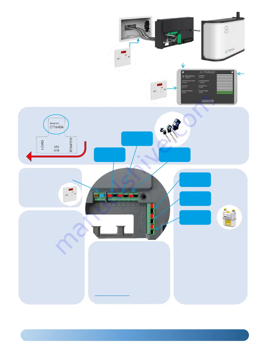
Please install current 

transducers in correct 

orientation as detailed 

on the device.

Note the CT size details for set up later.

CURRENT FLOW

The supply should be a 

3A Switched Fused 

Spur, marked to show 

its purpose and easily 

accessible.

When connecting current 
transducers:

Install 

single phase 

monitoring to 

channel one

.

For 3 phase CT follow L1, 
L2, L3 normal logical 
connection.

Channel 3 CT 

Connections

Channel 2 CT 

Connections

Channel 1 CT 

Connections

Channel 4 

PULSE ONLY

Channel 5 

PULSE ONLY

Channel 6 

PULSE &      

M-Bus

When connecting 

PULSE cables, start 

connections at 

channel 4 first 

before connecting 

to channel 5 & 6.  

Channel 6 is used for both PULSE & 
M-Bus (where fitted) inputs.

PLEASE NOTE:

The M-Bus functionality is enabled 
via the M-Bus menu in the 
Configuration Setup. If enabled, 
ensure no pulse connections are 
made on Channel 6

M-Bus wiring has no polarity

Unsupported meters that are 
discovered on the scan may need 
further setup to define the correct 
M-Bus records to report on. 

INSTALLATION TIPS

Cables between Netthings
controller and pulse enabled 
meters should be 

Belden 9501 

or equivalent.

Ensure gas meters that are 
pulse enabled are fitted with 
the appropriate pulse block. 
As there are several different 
types please ensure that the 
correct pulse block is ordered.

The Display and the Controller 
need to be within 5m of each 
other otherwise the WIFI 
communication may be 
unreliable.

The Energy Manager 

Controller

is typically 

mounted in a recessed 2-gang pattress box, 
however should the Controller be mounted in a 
surface box or directly to the wall, glands and 
cable restraints should be used as required. It is 
powered via a 3A Switched Fused Spur, marked 
to show its purpose and easily accessible.

(Example of a Recessed Box Installation)

The Energy Manager 

Display

should be mounted in a recessed 2-

gang pattress box and powered via a 3A Switched Fused Spur, 
marked to show its purpose and easily accessible. The power and 
reset button for the display can be accessed via the small hole on 
the top left of the display 

mount (5” Display) or the right hand side 

of the display mount

(7”

Display) with the supplied Allen key.

If you have any questions about installing this product please contact NetThings or visit www.netthings.co.uk

SUPPORTED M-Bus Meter 

Manufacturers

The following manufacturers of M-Bus 
meters are currently supported for use 
with Energy Manager. 

Diehl, GWF, Kamstrup, Sontex, Danfoss.

Please contact Netthings or visit 

www.netthings.co.uk

for further 

information

RESET 5”

INSTALLATION CONNECTIONS

RESET

7”

Summary of Contents for EMK-001 Series

Page 1: ...ENERGY MANAGER INSTALLATION USER GUIDE NetThings Ltd 14 New Mart Road Edinburgh EH14 1RL UK E info netthings co uk T 44 0 131 331 5445 Document 200SM075 Version 2 0 ...

Page 2: ...ION OVERVIEW 3 INSTALLATION CONNECTIONS 4 COMMISSIONING THE ENERGY MANAGER 5 USING THE ENERGY MANAGER 8 ADDITIONAL INFORMATION 10 SPECIFICATION 12 APPENDIX 1 M BUS INSTALLATION 13 APPENDIX 2 EVINOX INTEGRATION 15 ...

Page 3: ...he services you require to be monitored then run cabling between these positions during your first fix installation 3 Fix the Energy Manager and Display in their final positions and make power supply connections Make connections to the service you require to be monitored Note Additional equipment may be required to connect to other manufacturer s products Please contact NetThings if in doubt Pair ...

Page 4: ... appropriate pulse block As there are several different types please ensure that the correct pulse block is ordered The Display and the Controller need to be within 5m of each other otherwise the WIFI communication may be unreliable The Energy Manager Controller is typically mounted in a recessed 2 gang pattress box however should the Controller be mounted in a surface box or directly to the wall ...

Page 5: ...plied with the Controller The SSID and password to pair Controller and Display can found within the packaging and also on a label on the top of the controller Select the correct Energy Manager WIFI from the list displayed to pair the display The SSID will start with NT_ Enter the password for the chosen Controller Check the signal strength and press ASSOCIATE WIFI CONNECTION Alternative Method The...

Page 6: ...er to identify what is connected The Pulse Value field should be set to the corresponding value of the energy source that you are connecting to This value may be indicated on the connected energy source Press Save Channel Configuration before exiting and use setup button in the top right hand corner to return to the Configuration Menu SETTING UP PULSE INPUT CHANNELS CONFIGURATION Following a succe...

Page 7: ...correctly on the home display Typical example of an Electricity Connection Once all the channels have been verified press the setup menu icon to enter the Configuration menu and then press Overview Press Activate this Configuration if the Overview is correct IMPORTANT Once the system is fully commissioned and ready to be handed over the yellow warning banner should be removed by changing the banne...

Page 8: ...view our latest product range To return to the home screen at any point press the Home icon on the top left hand side of the display Channels that have been enabled during the commissioning process will now be visible Press the icon relating to the utility that you wish to monitor in order to see further information about your energy usage Channel number description and icon This section of the di...

Page 9: ...will not want to connect to the Energy Manager by default Windows 10 Example of available WIFI Please Note The procedure below is based on a Windows10 connection Other platforms will follow a similar process Enter the password that is found on the label on the Controller Your device will now connect to the Netthings Controller Open your web browser and enter 172 16 0 254 This Energy Manger should ...

Page 10: ... DATA ERASE Deletes viewable data Aggregate Config Data is preserved Allows WPS connection to the display or your device Allows Wi Fi channel changing from Channel1 to 6 or 11 Hold O button for 7 seconds Hold button for 3 seconds Hold button for 5 seconds NETWORK CONNECTIONS You do not need to have your home Wi Fi connected to the Energy Manager system in order for it to function The system broadc...

Page 11: ... generated by a transistor logic TTL output should have their polarity observed and maintained Meters with mechanical pulse outputs are not polarity dependant Breaks in the interconnecting cables from meters to Energy Manager Installing cables exceeding the distance specified in IEC 62053 31 100meters Installing incorrect pulse cable type Belden 9501 or similar is recommended Incorrectly connectin...

Page 12: ...rage Capacity Internal memory allowing storage for 10 years External microSD card slot for downloading data Power supply for display 5 8W Switching Power Supply I P 100 240VAC unterminated wire for spur connection O P DC 5V USB or barrel connector Dimensions 73mm x 30mm x 23 5mm Power supply for display 7 12W Switching Power Supply I P 100 240VAC unterminated wire for spur connection O P DC 5V bar...

Page 13: ... The scan results will show all meters that been discovered however a maximum of 3 will have a channel assigned When starting from an empty list the order in which meters are found and allocated channels is dependant on the sequence in which the devices communicate to the Energy Manager On subsequent refreshes if the meters found are the same serial number and model then the order is preserved The...

Page 14: ...rect and match up with the expected records to be read and their associated units Name This field can be changed by the installer to further identify the connected service Record This is the M Bus record that is being read on the connected meter It can be changed if it is incorrect or another record is required Type This is the type of connection being monitored for example Heat Cooling Water This...

Page 15: ...meter has been configured prior to connecting with an Evinox HIU the Evinox Configuration button will never appear NOTE Likewise after an Evinox HIU has been cabled to the Energy Manager M Bus configuration is no longer possible The M Bus configuration button will never appear Enter the Evinox Channel configuration by pressing Evinox Configuration The channel assignment page will be displayed Avai...

Page 16: ... manner from the channel configuration screen if desired otherwise there is no need for any further configuration SETTING UP EVINOX CHANNELS continued Click on Channels Configuration to view channels and select channels as required For Evinox assigned channels the name can be changed or the channel can be disabled but there are no other actions that can be performed from this screen Click on Save ...

Page 17: ...THIS PAGE IS INTENTIONALLY BLANK ...

Page 18: ...THIS PAGE IS INTENTIONALLY BLANK ...

Page 19: ...THIS PAGE IS INTENTIONALLY BLANK ...

Page 20: ...NetThings Ltd 14 New Mart Road Edinburgh EH14 1RL UK E info netthings co uk T 44 0 131 331 5445 ...

Reviews: