background image

Virtual Private Networks (VPN)   10-91

4.

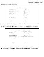
Click the 

TCP/IP Settings

 button. 

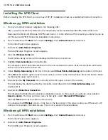
If your ISP uses dynamic IP addressing (DHCP), select the Ser ver assigned IP address radio button.

If your ISP uses static IP addressing, select the Specify an IP address radio button and enter your 
assigned IP address in the fields provided. Also enter the IP address in the Primar y and Secondar y 
DNS fields.

5.

Click the 

OK

 button in this window and the next two windows.

Summary of Contents for R910

Page 1: ...Netopia R910 Ethernet Router for DSL and Cable Modems User s Reference Guide ...

Page 2: ...may not be copied in whole or part without the prior written consent of Netopia Inc Under the law copying includes translation to another language or format Netopia Inc 2470 Mariner Square Loop Alameda CA 94501 1010 U S A Part Number For additional copies of this electronic manual order Netopia part number 6161087 PF 01 Printed Copies For printed copies of this manual order Netopia part number TER...

Page 3: ...4 Netopia R910 Ethernet Router back panel ports 3 15 Netopia R910 Ethernet Router status lights 3 16 Chapter 4 Connecting to Your Local Area Network 4 17 Overview 4 17 Network Model 4 17 Readying computers on your local network 4 18 Connecting to an Ethernet network 4 20 10Base T 4 20 Chapter 5 Configuring TCP IP 5 23 Hardware and operating system requirements 5 23 Configuring TCP IP on Windows 95...

Page 4: ...System Configuration 8 43 WAN configuration 8 43 System configuration screens 8 44 Navigating through the system configuration screens 8 45 System configuration features 8 46 IP setup 8 47 Filter sets firewalls 8 47 IP address serving 8 47 Date and time 8 47 Console configuration 8 48 SNMP Simple Network Management Protocol 8 48 Security 8 48 Upgrade feature set 8 48 Logging 8 49 Installing the Sy...

Page 5: ... 10 85 VPN QuickView 10 86 Dial Up Networking for VPN 10 88 Installing Dial Up Networking 10 88 Creating a new Dial Up Networking profile 10 89 Configuring a Dial Up Networking profile 10 90 Installing the VPN Client 10 92 Windows 95 VPN installation 10 92 Windows 98 VPN installation 10 92 Connecting using Dial Up Networking 10 93 About ATMP Tunnels 10 94 ATMP configuration 10 94 Allowing VPNs thr...

Page 6: ...ty measures 13 123 User accounts 13 123 Telnet access 13 125 About filters and filter sets 13 126 What s a filter and what s a filter set 13 126 How filter sets work 13 126 How individual filters work 13 128 Design guidelines 13 132 Working with IP filters and filter sets 13 133 Adding a filter set 13 134 Viewing filter sets 13 138 Modifying filter sets 13 139 Deleting a filter set 13 139 A sample...

Page 7: ... files 14 163 Transferring configuration and firmware files with XMODEM 14 163 Updating firmware 14 164 Downloading configuration files 14 165 Uploading configuration files 14 165 Restarting the system 14 166 Appendix A Troubleshooting A 167 Configuration problems A 167 Console connection problems A 168 Network problems A 168 How to reset the router to factory defaults A 169 Power outages A 169 Te...

Page 8: ...5 Packet header types B 185 Appendix C Understanding Netopia NAT Behavior C 187 Network configuration C 187 Background C 187 Exported services C 191 Important notes C 192 Configuration C 193 Summary C 194 Appendix D Binary Conversion Table D 195 Appendix E Further Reading E 197 Appendix F Technical Specifications and Safety Information F 201 Description F 201 Power requirements F 201 Environment F...

Page 9: ...ays on connection eliminates dialing and provides lower more predictable transmission costs Interconnects with cable modems or DSL modems or bridges that have an Ethernet port Connectivity to support Ethernet LANs via built in 4 port 10Base T hub Support for Network Address Translation NAT and MultiNAT allowing all computers and IP hosts on the LAN to appear as one or more IP addresses to the ISP ...

Page 10: ...u are performing If you prefer to work from hard copy rather than on line documentation you can also print out all of the manual or individual sections The pages are formatted to print on standard 8 1 2 by 11 inch paper We recommend that you print on three hole punched paper so you can put the pages in a binder for future reference For your convenience a printed copy can be purchased from Netopia ...

Page 11: ...SL and cable modems typically connect over Ethernet With Ethernet your ISP can offer you a service connecting one or more computers Using NAT and MultiNAT features you can configure your Netopia router to give all computers printers and other IP hosts access to the Internet using one or a limited number of IP addresses This means that you have more flexibility in selecting ISP account types The mo...

Page 12: ...ation If you are using NAT you should obtain the following If you are connecting to a remote site using Network Address Translation on your router your provider will not define the IP address information on your local LAN You can define this information based on an IP configuration that may already be in place for the existing network Alternatively you can use the default IP address range used by ...

Page 13: ...r the Netopia Router consider Available space and ease of installation Physical layout of the building and how to best use the physical space available for connecting your Netopia Router to the LAN Available wiring and jacks Distance from the point of installation to the next device length of cable or wall wiring Ease of access to the front of the unit for configuration and monitoring Ease of acce...

Page 14: ... This may be built in Ethernet or an add on card with TCP IP installed and configured See Hardware and operating system requirements on page 5 23 An Internet modem such as a cable modem or DSL bridge connected to the appropriate wall outlet for your Internet service source Your Internet connection device must have a 10Base T Ethernet port for connecting it to the router s Line port Identify the co...

Page 15: ...g table describes all the Netopia R910 Ethernet Router back panel ports Port Description Power port A mini DIN8 power adapter cable connection Line port The dedicated Ethernet port for your connection to your Internet connection device s Ethernet port Console port A DB 9 console port for a direct serial connection to the console screens You can use this if you are an experienced user See Connectin...

Page 16: ...s green The WAN interface is inactive 9 is off The WAN interface detects a failure after line activation 9 flashes red Calls are setting up 10 flashes green Data calls connect 10 is green The line is carrying data traffic 10 flashes orange The Ethernet port is connected to the LAN 14 15 16 and 17 are green There is activity on the respective Ethernet ports 14 15 16 and 17 flash green Note The Chan...

Page 17: ...rly configured You can customize the router s configuration for your particular LAN requirements using console based management see Console Based Management on page 6 31 This section covers the following topics Overview on page 4 17 Readying computers on your local network on page 4 18 Connecting to an Ethernet network on page 4 20 Overview You can connect the Netopia R910 to an IP network that us...

Page 18: ... network model is typical other network models are possible For example you may choose to attach the Ethernet WAN port to an external Ethernet hub connected to a number of workstations Readying computers on your local network PC and Macintosh computers must have certain components installed before they can communicate through the Netopia R910 The following illustration shows the minimal requiremen...

Page 19: ... TCP IP stacks available for PC computers Windows 95 includes a built in TCP IP stack See Configuring TCP IP on Windows 95 or 98 on page 5 24 Macintosh computers use either MacTCP or Open Transport See Configuring TCP IP on a Macintosh Computer on page 5 26 Ethernet Ethernet hardware and software drivers enable your PC or Macintosh computer to communicate on the LAN EtherTalk This is an AppleTalk ...

Page 20: ...ome important attributes of these connections 10Base T You can connect a standard 10Base T Ethernet network to the Netopia R910 using any of its available Ethernet ports Netopia R910 Ethernet Router back panel Attribute 10Base T Max length of backbone branch or end to end cable length 330 feet 100 meters Cable type Twisted pair 10Base T Netopia R910 port used Ethernet Other restrictions No daisy c...

Page 21: ...work to the Netopia R910 through an Ethernet port use a 10Base T cable with RJ 45 connectors If you have more than four devices to connect you can attach additional devices using a 10Base T hub using a cross over cable The Netopia R910 in a 10Base T network with a hub Ethernet 10BASE T Hub 10BASE T Hub Ethernet ...

Page 22: ...4 22 User s Reference Guide ...

Page 23: ...opics Hardware and operating system requirements on page 5 23 Configuring TCP IP on Windows 95 or 98 on page 5 24 Configuring TCP IP on a Macintosh Computer on page 5 26 If after following the instructions in this section you are having difficulties configuring the router see Appendix A Troubleshooting Hardware and operating system requirements Before you can configure your router make sure your c...

Page 24: ...ecommended The easiest configuration method is to accept the dynamic IP address assigned by your router Dynamic Host Configuration Protocol DHCP which enables dynamic addressing is enabled by default on the router 1 Go to Start Menu Settings Control Panels and double click the Network icon From the Network components list select the Configuration tab 2 Select TCP IP Your Network Card Then select P...

Page 25: ... the following IP Address 192 168 1 2 Subnet Mask 255 255 255 0 Your ISP or network administrator may ask you to use a different IP address and subnet mask 3 Click on the Gateway tab shown at right Under New gateway enter 192 168 1 1 Click Add This is the address that is assigned to the Netopia R910 4 Click on the DNS Configuration tab Click Enable DNS Enter the following information Host Type the...

Page 26: ...resses using MacTCP however to do so requires that the optional AppleTalk kit be installed and this can only be done after the router is configured You must have built in Ethernet or a third party Ethernet card and its associated drivers installed in your Macintosh Dynamic configuration recommended The easiest configuration method is to accept the dynamic IP address assigned by your router DHCP wh...

Page 27: ...tion into the fields as shown in the table at right 4 Close the TCP IP or MacTCP control panel and save the settings 5 If you are using MacTCP you must restart the computer If you are using Open Transport you do not need to restart These are the only fields you need to modify in this screen Option Select Type Connect via Ethernet Configure Manually IP Address 192 168 1 2 Subnet mask 255 255 255 0 ...

Page 28: ...ng Open Transport TCP IP 1 Go to the Apple menu Select Control Panels and then TCP IP 2 With the TCP IP window open go to the Edit menu and select User Mode Choose Advanced and click OK 3 In the TCP IP window select or type information into the fields as shown in the following table 4 Close the TCP IP control panel and save the settings These are the only fields you need to modify in these screens...

Page 29: ...t an available zone then click the More button In the MacTCP More window select the Server radio button If necessary fill in the Domain Name Server Information given to you by your administrator 5 Restart the computer These are the only fields you need to modify in these screens Note More information about configuring your Macintosh computer for TCP IP connectivity through a Netopia R910 can be fo...

Page 30: ...5 30 User s Reference Guide ...

Page 31: ...reens on page 6 34 Console based management screens contain seven entry points to the Netopia Router configuration and monitoring features The entry points are displayed in the Main Menu shown below The Easy Setup menus display and permit changing the values contained in the default WAN and IP configuration Experienced users can use Easy Setup to initially configure the router directly through a c...

Page 32: ...tables and device logs that show information about your router your network and their history See Chapter 12 Monitoring Tools for detailed information The Quick Menus screen is a shortcut entry point to a wide variety of the most commonly used configuration menus that are accessed through the other menu entry points The Quick View menu displays at a glance current real time operating information a...

Page 33: ...ware such as HyperTerminal provided with Windows95 on the PC or ZTerm included on the Netopia CD for Macintosh computers The Netopia R910 back panel has a connector labeled Console for attaching the Router to either a PC or Macintosh computer via the serial port on the computer On a Macintosh computer the serial port is called the Modem port or Printer port This connection lets you use the compute...

Page 34: ...uter firmware contains an autobaud detection feature If you are at any screen on the serial console you can change your baud rate and press Return HyperTerminal for the PC requires a disconnect The new baud rate is displayed at the bottom of the screen To Use These Keys Move through selectable items in a screen or pop up menu Up Down Left and Right Arrow To set a change to a selected item or open ...

Page 35: ...ses and IP address serving Password protect configuration access to your Netopia R910 Ethernet Router Accessing the Easy Setup console screens To access the console screens Telnet to the Netopia Router over your Ethernet network or physically connect with a serial console cable and access the Netopia Router with a terminal emulation program See Connecting through a Telnet session on page 6 32 or C...

Page 36: ...ia the Console port your computer s serial port is not being used by another device such as an internal modem or an application Turn off all other programs other than your terminal emulation program that may be interfering with your access to the port You have entered the correct password if necessary Your Netopia R910 s console access may be password protected from a previous configuration See yo...

Page 37: ... your ISP doesn t support DHCP Some ISPs may not be running a DHCP server In this case they may simply assign your router a Static IP Address and will supply you with several values for you to enter into the Router The ISP will provide the values shown below You can record these values print this page and use the spaces above If your ISP assigns your Router a Static IP address do the following 1 F...

Page 38: ...address your ISP gave you Press Return A new field Secondary Domain Name Server will appear If your ISP gave you a secondary domain name server address enter it here Press Return until the next field Default IP Gateway is highlighted 10 Enter the Default IP Gateway address your ISP gave you Press Return 11 Press the Down arrow key until you reach NEXT SCREEN Press Return 12 Do this again through t...

Page 39: ...ault 2 To manually configure an IP address for use on the Ethernet WAN port select Local WAN IP Address and enter the IP address you want to use Otherwise accept the default value 0 0 0 0 If you accept the default the Netopia R910 Ethernet Router will act as a DHCP client on the Ethernet WAN port and attempt to acquire an address from a DHCP server By default the router acts as a DHCP client on th...

Page 40: ...s 192 168 1 1 Because this is a private network address it should never be directly connected to the Internet Using NAT for all your WAN and IP configurations will ensure this restriction See IP Setup and Network Address Translation on page 9 51 of this guide for more information 2 Select Ethernet Subnet Mask and enter the subnet mask your ISP has given you The Ethernet Subnet Mask defaults to a s...

Page 41: ...Easy Setup Security Configuration The Easy Setup Security Configuration screen lets you password protect your Netopia R910 Input your Write Access Name and Write Access Password with names or numbers totaling up to eleven digits If you password protect the console screens you will be prompted to enter the name and password you have specified every time you log in to the console screens Do not forg...

Page 42: ...lect CONTINUE to restart the Netopia Router and have your selections take effect Note You can also restart the system at any time by using the Restart System utility see Restarting the system on page 14 166 or by turning the Netopia Router off and on with the power switch Easy Setup is now complete ...

Page 43: ...gement screens This section covers the following topics WAN configuration on page 8 43 System configuration screens on page 8 44 Navigating through the system configuration screens on page 8 45 System configuration features on page 8 46 WAN configuration To configure your Wide Area Network WAN connection navigate to the WAN Configuration screen from the Main Menu and select WAN Configuration then ...

Page 44: ...o Both the default the Netopia R910 will accept information from either RIP v1 or v2 routers Alternatively select Receive RIP and select v1 or v2 from the popup menu With Receive RIP set to v1 the Netopia R910 s Ethernet port will accept routing information provided by RIP packets from other routers that use the same subnet mask Set to v2 the Netopia R910 will accept routing information provided b...

Page 45: ... shows how to get to the Network Protocols Setup screens The path guide represents these steps 1 Beginning in the Main Menu select System Configuration and press Return The System Configuration screen appears 2 Select IP Setup and press Return The IP Setup screen appears To go back in this sequence of screens use the Escape key Netopia R910 v4 8 Easy Setup WAN Configuration System Configuration Ut...

Page 46: ...ore of these needs use the system configuration options described in later chapters System configuration of dynamic IP address distribution through DHCP or BootP Greater network security through the use of filters To access the system configuration screens select System Configuration in the Main Menu then press Return The System Configuration menu screen appears System Configuration IP Setup Filte...

Page 47: ...ime You can set the system s date and time in the Set Date and Time screen Select Date and Time in the System Configuration screen and press Return The Set Date and Time screen appears Follow these steps to set the system s date and time 1 Select Current Date and enter the date in the appropriate format Use one or two digit numbers for the month and day and the last two digits of the current year ...

Page 48: ...ter 3 Select SET CONFIG NOW to save the new parameter settings Select CANCEL to leave the parameters unchanged and exit the Console Configuration screen SNMP Simple Network Management Protocol These screens allow you to monitor and configure your network by means of a standard Simple Network Management Protocol SNMP agent Details are given in SNMP on page 12 118 Security These screens allow you to...

Page 49: ...ng Configuration screen appears By default all events are logged in the event history By toggling each event descriptor either Yes or No you can determine which ones are logged and which are ignored You can enable or disable the syslog client dynamically When enabled it will report any appropriate and previously unreported events You can specify the syslog server s address either in dotted decimal...

Page 50: ...14 06 tsnext netopia com Device restarted Nov 5 10 14 06 tsnext netopia com Received Speech Setup Ind from DN not supplied Nov 5 10 14 06 tsnext netopia com Requested Connect to our DN 5108645534 Nov 5 10 14 06 tsnext netopia com ASYNC Modem carrier detected more Modem reports 26400 V34 Nov 5 10 14 06 tsnext netopia com WAN 56K Modem 1 activated at 115 Kbps Nov 5 10 14 06 tsnext netopia com Connec...

Page 51: ...slation feature This section covers the following topics Network Address Translation features on page 9 51 Using Network Address Translation on page 9 53 IP setup on page 9 56 IP address serving on page 9 66 Network Address Translation allows communication between the LAN connected to the Netopia R910 and the Internet using a single IP address instead of a routed account with separate IP addresses...

Page 52: ...Web FTP or other services available to the WAN To support these services with NAT enabled a service can be associated with only one machine on the LAN When connected to the Internet or some other large network using Network Address Translation the individual machines on your LAN are not directly accessible from the WAN NAT provides an inherently secure method of connection to the outside world 163...

Page 53: ...s on your LAN For example you could assign 10 0 0 1 to your Netopia R910 10 0 0 2 to a node running as a World Wide Web server 10 0 0 3 to an FTP server 10 0 0 4 to a Windows NT PC 10 0 0 5 to a Windows 95 PC Note See Associating port numbers with nodes on page 9 55 3 By default Network Address Translation is enabled in the Netopia R910 If you disabled it and now want to reenable it From the WAN C...

Page 54: ...ing select Local WAN IP Address and enter the local WAN address your ISP gave you Then select Local WAN IP Mask and enter the WAN subnet mask of the remote site you will connect to The default address is 0 0 0 0 which allows for dynamic addressing meaning that your ISP assigns an address via DHCP each time you connect However if you want to use static addressing enter a specific address WAN Ethern...

Page 55: ...arious services For example Web servers typically use port number 80 All FTP servers use port number 21 Telnet uses port number 23 SNMP uses port number 161 To help direct incoming IP traffic to the appropriate server the Netopia R910 lets you associate these and other port numbers with distinct IP addresses on your internal LAN using exported services See IP setup on page 9 56 for details Network...

Page 56: ...910 Select Ethernet IP Address and enter the IP address for the Netopia R910 s Ethernet port Select Ethernet Subnet Mask and enter the subnet mask for the Ethernet IP address that you entered in the last step If you desire multiple subnets select Define Additional Subnets If you select this item you will be taken to the IP Subnets screen This screen allows you to define IP addresses and masks for ...

Page 57: ...Routing Information Protocol RIP is needed if there are IP routers on other segments of your Ethernet network that the Netopia R910 needs to recognize If this is the case select Receive RIP and select v1 v2 or Both from the popup menu With Receive RIP set to v1 the Netopia R910 s Ethernet port will accept routing information provided by RIP packets from other routers that use the same subnet mask ...

Page 58: ...he Add Exported Service screen appears Exported Services Local Port to IP Address Remapping Show Change Exports Add Export Delete Export Return Enter to configure UDP TCP Port to IP Address redirection Add Exported Service Service Local Server s IP Address 0 0 0 0 ADD EXPORT NOW CANCEL ...

Page 59: ... address 10 0 0 2 Some services such as Timbuktu require the export of multiple TCP ports When you associate Timbuktu with a local server or Timbuktu host all of the major Timbuktu services are exported i e Observe Control Send and Exchange Note If the TCP port of a service you want to use is not listed you can add it by selecting Other on the pop up menu Add Exported Service Type Port Service ftp...

Page 60: ...eight Ethernet IP subnets on unlimited user models one primary subnet and up to seven secondary subnets by entering IP address subnet mask pairs IP Setup Ethernet IP Address 192 128 117 162 Ethernet Subnet Mask 255 255 255 0 Define Additional Subnets Default IP Gateway 192 128 117 163 Primary Domain Name Server 0 0 0 0 Secondary Domain Name Server 0 0 0 0 Domain Name Receive RIP Both Transmit RIP ...

Page 61: ...onfigured To add an IP subnet enter the Netopia R910 s IP address on the subnet in the IP Address field in a particular row and the subnet mask for the subnet in the Subnet Mask field in that row For example To delete a configured subnet set both the IP address and subnet mask values to 0 0 0 0 either explicitly or by clearing each field and pressing Return or Enter to commit the change When a con...

Page 62: ... to reach a particular network However static routes are used only if they appear in the IP routing table which contains all of the routes used by the Netopia R910 see IP routing table on page 12 115 Static routes are helpful in situations where a route to a network must be used and other means of finding the route are unavailable For example static routes are useful when you cannot rely on RIP To...

Page 63: ... shown below will appear The table has the following columns Dest Network The network IP address of the destination network Static Routes Display Change Static Route Add Static Route Delete Static Route Configure View Delete Static Routes from this and the following Screens Dest Network Subnet Mask Next Gateway Priority Enabled 0 0 0 0 0 0 0 0 163 176 8 1 Low Yes Select a Static Route to modify ...

Page 64: ... Select Destination Network IP Address and enter the network IP address of the destination network Select Destination Network Subnet Mask and enter the subnet mask used by the destination network Select Next Gateway IP Address and enter the IP address for the router that the Netopia R910 will use to reach the destination network This router does not necessarily have to be part of the destination n...

Page 65: ...een are the same as the ones in the Add Static Route screen see Adding a static route on page 9 64 Deleting a static route To delete a static route in the Static Routes screen select Delete Static Route to display a table of static routes Select a static route from the table and press Return to delete it To exit the table without deleting the selected static route press Escape Rules of static rout...

Page 66: ...owever in contrast BootP address assignments are permanent since there is no lease renewal mechanism in BootP The third protocol called Dynamic WAN is part of the PPP MP suite of wide area protocols used for WAN connections It allows remote terminal adapters and NAT enabled routers to be assigned a temporary IP address for the duration of their connection Since no two hosts can use the same IP add...

Page 67: ...ample Your ISP has given your Netopia R910 the IP address 192 168 6 137 with a subnet mask of 255 255 255 248 The subnet mask allocated will give you six IP addresses to use when connecting to the ISP over the Internet for more information on IP addressing refer to Appendix B Understanding IP Addressing Your address range will be from 137 143 In this example you would enter 192 168 6 138 as the 1s...

Page 68: ...face address on the subnet You can edit the remaining columns in each row The 1st Client Addr and Clients columns allow you to specify the base and extent of the address serving pool for a particular subnet Entering 0 0 0 0 for the first client address or 0 for the number of clients indicates that no addresses will be served from the corresponding Ethernet IP subnet The Client Gateway column allow...

Page 69: ...uest if the address is available The client stores this address in non volatile storage for example on disk and the specific storage method location differs depending on the client operating system When requesting an address a client may provide a client identifier or if it does not the Netopia R910 may construct a pseudo client identifier for the client When the client subsequently requests an ad...

Page 70: ...NetBIOS a non IBM network operating system or network interface card must offer a NetBIOS emulator Many vendors either provide a version of NetBIOS to interface with their hardware or emulate its transport layer communications services in their network products A NetBIOS emulator is a program provided by NetWare clients that allow workstations to run applications that support IBM s NetBIOS calls S...

Page 71: ...are now finished setting up DHCP NetBIOS Options To return to the IP Address Serving screen press Escape To enable BootP s address serving capability select Serve BOOTP Clients and toggle to Yes Note Addresses assigned through BootP are permanently allocated from the IP Address Serving pool until you release them To release these addresses navigate back to the Main Menu then Statistics Logs Served...

Page 72: ...e Select Release BootP Leases and press Return You have finished your IP setup IP Address Lease Management Reset All Leases Release BootP Leases Reclaim Declined Addresses Hit RETURN ENTER you will return to the previous screen ...

Page 73: ...r picks up the phone to call her daughter at college at the same time you are talking to your relatives your calls don t overlap but each is separate and private Neither house has a direct wire to the places they call Both share the same lines on the telephone poles or underground on the street These calls are virtual private networks Virtual because they appear to be direct connections between th...

Page 74: ... client a Netopia R series router can provide all users on a LAN with secure access over the Internet to the resources of another LAN by setting up a tunnel with a Windows NT server running Remote Access Services RAS or with another Netopia Router As a server a Netopia R series router can provide remote users a secure connection to the resources of the LAN over a dial up cable DSL or any other typ...

Page 75: ...e You must choose which protocol you will be using since you cannot both export PPTP and use ATMP or vice versa at the same time Having both an ATMP tunnel and a PPTP export is not possible because both functions require GRE and the router s PPTP export server does not distinguish the GRE packets it forwards Since it processes all of them ATMP tunneling is impaired For example you cannot run an AT...

Page 76: ... PPTP is a Datalink Encapsulation option in Connection Profiles It is not an option in device or link configuration screens as PPTP is not a native encapsulation Consequently the Easy Setup Profile does not offer PPTP datalink encapsulation Note The Netopia R910 Router has access to Connection Profiles for tunnelling purposes If the PPP dialup kit is not installed you cannot use PPP as a datalink ...

Page 77: ...eway field allows this path to be resolved You can specify a Data Compression algorithm either None or Standard LZS for the PPTP connection Note When the Authentication protocol is MS CHAP compression is set to None and the Data Compression option is hidden From the pop up menu select an Authentication protocol for the PPP connection Options are PAP CHAP or MS CHAP The default is PAP The authentic...

Page 78: ...P client You can specify that this router will Initiate Connections acting as a PAC or only answer them acting as a PNS Tunnels are normally initiated On Demand however you can disable this feature When disabled the tunnel must be manually established via the call management screens or may be scheduled using the scheduled connections feature Some networks that use Microsoft Windows NT PPTP Network...

Page 79: ...g it difficult for any third party to get at the original data Netopia PPTP is fully compatible with Microsoft Point to Point Encryption MPPE data encryption for user data transfer over the PPTP tunnel Microsoft Windows NT Server provides MPPE encryption capability only when Microsoft Challenge Handshake Authentication Protocol MS CHAP is enabled Netopia complies with this feature to allow MPPE on...

Page 80: ...APv2 the Netopia router will fall back to MS CHAPv1 or if the router or VPN adapter client you are connecting to does not support MPPE at all the PPP session will be dropped This is done automatically and transparently About IPsec Tunnels IPsec stands for IP Security a set of protocols that supports secure exchange of IP packets at the IP layer IPsec is deployed widely to implement VPNs IPsec supp...

Page 81: ...nnection Profile You must specify an Encryption Transform The choices are DES or NULL The default is DES Add Connection Profile Profile Name Profile 1 Profile Enabled Data Link Encapsulation PPP RFC1483 ATMP IP Enabled PPTP IP Profile Parameters IPsec Interface Group Primary COMMIT CANCEL IPsec Encryption Authentication Options Encryption Transform DES Encryption Key NULL Authentication Type ESP A...

Page 82: ...ntication Key if the Authentication Type is anything other than None The key must be an ASCII string of up to 48 characters for both HMAC MD5 96 and HMAC SHA1 96 Key The key is a hexadecimal entry of 16 bytes 32 characters of input for MD5 and 20 bytes 40 characters of input for SHA1 It is not possible to view the Encryption Keys or Authentication Key once they have been set You can specify a Comp...

Page 83: ...fy a Remote Members Network address This specifies the subnet of the remote IPsec tunnel and will be used with the Remote Members Mask to determine and set the route You must specify a Remote Members Mask This is the subnet mask of the remote subnet to which the IPsec tunnel will route You can specify Address Translation Enabled For more information see Chapter 9 IP Setup and Network Address Trans...

Page 84: ...sted The value must be unique over the set of all AH SPIs specified for the remote tunnel endpoint You can specify a Local Tunnel Endpoint Address If not 0 0 0 0 this value must be one of the assigned interface addresses either WAN or LAN This is used as the source address of all IPsec traffic You can specify a Next Hop Gateway If you specify the Remote Tunnel Endpoint Address and the address is i...

Page 85: ...nections select VPN Default Answer Profile and press Return The Default VPN Profile screen appears Toggle Answer VPN Connections to Yes if you want the router to accept VPN connections or No the default if you do not This applies to both ATMP and PPTP connections WAN Configuration WAN Wide Area Network Setup Display Change Connection Profile Add Connection Profile Delete Connection Profile WAN Def...

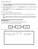
Page 86: ...c Tunnels AH is not supported through an interface that has NAT applied to it NAT may be applied to the inner payload AH is not supported through an interface which is either Unnumbered or Numbered with a dynamically assigned address unless the Local Tunnel Endpoint address is specified in the Advanced IP Profile Options screen V V V VP P P PN N N N Q Q Q Qu u u ui i i ic c c ck k k kV V V Vi i i ...

Page 87: ...s the data link encapsulation method PPTP or ATMP Rx Pckts Shows the number of packets received via the VPN tunnel Tx Pckts Shows the number of packets transmitted via the VPN tunnel Est Indicates whether the connection was locally Lcl or remotely Rmt established Partner Address Shows the tunnel partner s IP address ...

Page 88: ...d comes standard with Windows 98 and Windows NT The VPN tunnel behaves as a private network connection unrelated to other traffic on the network Once you have installed Dial Up Networking you will be able to connect to your remote site as if you had a direct private connection regardless of the intervening network s through which your data passes You may need to install the Dial Up Networking feat...

Page 89: ...ofile with the Make New Connection feature Do the following 1 Double click the My Computer or whatever you have named it icon on your desktop Open the Dial Up Networking folder and then double click Make New Connection The Make New Connection wizard window appears 2 Type a name for this connection such as the name of your company or the computer you are dialing into From the pull down menu select ...

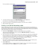
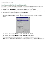
Page 90: ...atever you have named it icon on your desktop Open the Dial Up Networking folder You will see the icon for the profile you created in the previous section 2 Right click the icon and from the pop up menu select Properties 3 In the Properties window click the Server Type button From the Type of Dial up Server pull down menu select the appropriate type of server for your system version Windows 95 use...

Page 91: ...lect the Server assigned IP address radio button If your ISP uses static IP addressing select the Specify an IP address radio button and enter your assigned IP address in the fields provided Also enter the IP address in the Primary and Secondary DNS fields 5 Click the OK button in this window and the next two windows ...

Page 92: ...or the communications option Active components will have a check in the checkboxes to their left 6 Check Dial Up Networking at the top of the list and Virtual Private Networking at the bottom of the list 7 Click OK at the bottom right on each screen until you return to the Control Panel Close the Control Panel by clicking the upper right corner X 8 Double click the My Computer icon normally at the...

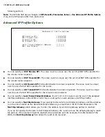
Page 93: ...the Make New Connection installation screen In this screen you will see a box labelled Select a device From the pull down menu to the right select Microsoft VPN Adapter Click the Next button at the bottom of the screen This displays the VPN Host screen In the box to the top center of the screen enter your VPN server s IP address for example 192 168 xxx xxx This is not a proper Internet address C C...

Page 94: ...the client data within Generic Routing Encapsulation GRE The GRE data is then routed using standard methods A A A AT T T TM M M MP P P P c c c co o o on n n nf f f fi i i ig g g gu u u ur r r ra a a at t t ti i i io o o on n n n ATMP is a Datalink Encapsulation option in Connection Profiles It is not an option in device or link configuration screens since ATMP is not a native encapsulation The Eas...

Page 95: ... Partner IP Address specifies the address of the other end of the tunnel When unspecified the gateway can not initiate tunnels i e act as a foreign agent for this profile it can only accept tunnel requests as a home agent Add Connection Profile Profile Name Profile 1 Profile Enabled Data Link Encapsulation PPP Data Link Options Frame Relay ATM FUNI IP Enabled ATMP IP Profile Parameters PPTP COMMIT...

Page 96: ...uthenticating the tunnel Note The Password entry will be the same for both ends of the tunnel For Netopia to Netopia connections only you can specify a Data Encryption algorithm for the ATMP connection from the pop up menu either DES or None None is the default Note Ascend does not support DES encryption for ATMP tunnels You must specify an 8 byte Key String when DES is selected When encryption is...

Page 97: ... be discarded rather than being processed by NAT Ordinarily Ping is an excellent troubleshooting tool but it will not be effective in this circumstance Instead use another TCP or UDP based network service for troubleshooting Since the Netopia Router is capable of serving Telnet and HTTP we recommend using these services instead of Ping IP Profile Parameters Address Translation Enabled Yes NAT Map ...

Page 98: ...ed In order to ensure that a firewall will allow a VPN certain attributes must be added to the firewall s provisioning The provisions necessary vary slightly between ATMP and PPTP but both protocols operate on the same basic premise there are control and negotiation operations and there is the tunnelled traffic that carries the payload of data between the VPN endpoints The difference is that ATMP ...

Page 99: ...ate to Display Change IP Filter Set and from the pop up menu select Basic Firewall Select Display Change Input Filter Display Change Input Filter screen For Input Filter 1 set the Destination Port information as shown below Main Menu System Filter Sets IP Filter Sets Display Change IP Filter Set Configuration Basic Firewall Source IP Addr Dest IP Addr Proto Src Port D Port On Fwd 1 0 0 0 0 0 0 0 0...

Page 100: ...s Source IP Address 0 0 0 0 Source IP Address Mask 0 0 0 0 Dest IP Address 0 0 0 0 Dest IP Address Mask 0 0 0 0 Protocol Type GRE Source IP Addr Dest IP Addr Proto Src Port D Port On Fwd 1 0 0 0 0 0 0 0 0 TCP NC 1723 Yes Yes 2 0 0 0 0 0 0 0 0 GRE Yes Yes Change Output Filter 1 Enabled Yes Forward Yes Source IP Address 0 0 0 0 Source IP Address Mask 0 0 0 0 Dest IP Address 0 0 0 0 Dest IP Address M...

Page 101: ... Output Filter 2 set the Protocol Type to allow GRE as shown below Change Output Filter 2 Enabled Yes Forward Yes Source IP Address 0 0 0 0 Source IP Address Mask 0 0 0 0 Dest IP Address 0 0 0 0 Dest IP Address Mask 0 0 0 0 Protocol Type GRE ...

Page 102: ... From the Main Menu navigate to Display Change IP Filter Set and from the pop up menu select Basic Firewall Select Display Change Input Filter Display Change Input Filter screen For Input Filter 1 set the Destination Port information as shown below Main Menu System Filter Sets IP Filter Sets Display Change IP Filter Set Configuration Basic Firewall Source IP Addr Dest IP Addr Proto Src Port D Port...

Page 103: ...ed Yes Forward Yes Source IP Address 0 0 0 0 Source IP Address Mask 0 0 0 0 Dest IP Address 0 0 0 0 Dest IP Address Mask 0 0 0 0 Protocol Type GRE Source IP Addr Dest IP Addr Proto Src Port D Port On Fwd 1 0 0 0 0 0 0 0 0 UDP NC NC Yes Yes 2 0 0 0 0 0 0 0 0 GRE Yes Yes Change Output Filter 1 Enabled Yes Forward Yes Source IP Address 0 0 0 0 Source IP Address Mask 0 0 0 0 Dest IP Address 0 0 0 0 De...

Page 104: ...tput Filter 2 set the Protocol Type to allow GRE as shown below Change Output Filter 2 Enabled Yes Forward Yes Source IP Address 0 0 0 0 Source IP Address Mask 0 0 0 0 Dest IP Address 0 0 0 0 Dest IP Address Mask 0 0 0 0 Protocol Type GRE ...

Page 105: ...tion in your R910 you first enable PPP over Ethernet and then create a Connection Profile for your Internet connection From the Main Menu select WAN Configuration WAN Setup and then EN Wan Module 1 Setup Press Return The WAN Ethernet Configuration screen appears Toggle Enable PPP over Ethernet to On using the Tab key Press Return and then Escape twice to return to WAN Configuration Select Add Conn...

Page 106: ...ion information to connect to your ISP s service Add Connection Profile Profile Name My_ISP Profile Enabled Yes Data Link Encapsulation PPP Data Link Options IP Enabled Yes IP Profile Parameters Interface Group Primary COMMIT CANCEL Configure a new Conn Profile Finished ADD or CANCEL to exit Datalink PPP MP Options Data Compression Standard LZS Send Authentication PAP Send User Name jagdip Send Pa...

Page 107: ... base and extent of the address serving pool This allows you to otherwise configure address serving as you please using the normal address serving configuration items For example if you disable address serving the router will not enable address serving when it reconfigures the address serving pool C C C Co o o on n n nf f f fi i i ig g g gu u u ur r r ra a a at t t ti i i io o o on n n n To enable...

Page 108: ... Default IP Gateway 163 176 12 1 CPU Load 6 Unused Memory 232 KB Primary DNS Server 163 176 4 31 WAN Interface Group EN Secondary DNS Server 163 176 4 10 Domain Name isp com MAC Address IP Address Ethernet Hub 00 00 c5 78 5d 10 192 168 1 1 Ethernet WAN1 00 00 c5 78 5d 12 0 0 0 0 Current WAN Connection Status Profile Name Rate Use Remote Address Est More Info VPN QuickView LED Status PWR WAN1 CON A...

Page 109: ...overs the following topics Quick View status overview on page 12 109 Statistics Logs on page 12 111 Event histories on page 12 112 Routing tables on page 12 114 Served IP Addresses on page 12 116 System Information on page 12 117 SNMP on page 12 118 Quick View status overview You can get a useful overall status report from the Netopia R910 in the Quick View screen To go to the Quick View screen se...

Page 110: ...etopia R910 s hardware address IP Address The Netopia R910 s IP address entered in the IP Setup screen Status lights This section shows the current real time status of the Netopia R910 s status lights LEDs It is useful for remotely monitoring the router s status The Quick View screen s arrangement of LEDs corresponds to the physical arrangement of LEDs on the router Quick View 12 14 1998 01 13 52 ...

Page 111: ... Logs and select one of the options described in the sections below General Statistics To go to the General Statistics screen select General Statistics and press Return The General Statistics screen appears The General Statistics screen displays information about data traffic on the Netopia R910 s data ports This information is useful for monitoring and troubleshooting your LAN Note that the count...

Page 112: ... packets are transmitted simultaneously by nodes on the LAN Event histories The Netopia R910 records certain relevant occurrences in event histories Event histories are useful for diagnosing problems because they list what happened before during and after a problem occurs You can view two different event histories one for the router s system and one for the WAN The Netopia R910 s built in battery ...

Page 113: ... in the WAN Event History select the event and then press Return A dialog box containing more information about the selected event will appear Press Return or Escape to dismiss the dialog box To clear the event history select Clear History at the bottom of the history screen and press Return Device Event History The Device Event History screen lists a total of 128 port and system events giving the...

Page 114: ...time the screen is first invoked To take a new snapshot select Update at the bottom of the screen and press Return Device Event History Current Date 12 11 98 12 26 39 PM Date Time Event SCROLL UP 08 11 98 12 25 28 Telnet connection up address 163 176 8 134 08 11 98 12 25 05 IP address server configuration error server disabled 08 11 98 12 25 05 IP Route 0 0 0 0 0 0 0 0 not installed 08 11 98 12 25...

Page 115: ...ROLL DOWN at the bottom of the table and press Return Statistics Logs WAN Event History Device Event History IP Routing Table Served IP Addresses General Statistics System Information IP Routing Table Network Address Subnet Mask via Router Port Type SCROLL UP 0 0 0 0 255 0 0 0 0 0 0 0 Other 127 0 0 1 255 255 255 255 127 0 0 1 Loopback Local 192 168 1 0 255 255 255 240 192 168 1 1 Ethernet Local 19...

Page 116: ...ppears Served IP Addresses IP Address Type Expires Client Identifier SCROLL UP 192 168 1 100 DHCP 00 36 EN 00 00 c5 4a 1f ea 192 168 1 101 DHCP 00 58 EN 08 00 07 16 0c 85 192 168 1 102 192 168 1 103 192 168 1 104 192 168 1 105 192 168 1 106 192 168 1 107 192 168 1 108 192 168 1 109 192 168 1 110 192 168 1 111 192 168 1 112 192 168 1 113 SCROLL DOWN Lease Management EN Ethernet Address AT AppleTalk...

Page 117: ...no longer be on the network System Information The System Information screen gives a summary view of the general system level values in the Netopia R910 Ethernet Router From the Statistics Logs menu select System Information The System Information screen appears The information display varies by model firmware version feature set and so on You can tell at a glance your particular system configurat...

Page 118: ...in the order they are listed here Follow the instructions included with your SNMP manager on how to load MIBs The SNMP Setup screen From the Main Menu select SNMP in the System Configuration screen and press Return The SNMP Setup screen appears Follow these steps to configure the first three items in the screen 1 Select System Name and enter a descriptive name for the Netopia R910 s SNMP agent Sys...

Page 119: ...iously if either community string was the empty string SNMP Requests specifying an empty community string were accepted and processed This change is designed to allow the administrator to block SNMP access to the router and to provide more granular control over the allowed SNMP operations to the router Setting only the Read Write community string to the empty string will block SNMP Set Requests to...

Page 120: ...iver 2 Select Receiver IP Address or Domain Name Enter the IP address or domain name of the SNMP manager you want to receive the trap 3 Select Community String Enter whatever community string is appropriate for the traps to be sent to the management station whose IP address or domain name you entered on the previous line 4 Select Add Trap Receiver Now and press Return You can add up to seven more ...

Page 121: ... Trap Receiver screen edit the information as needed and press Return Deleting IP trap receivers 1 To delete an IP trap receiver select Delete IP Trap Receiver in the IP Trap Receivers screen 2 Select an IP trap receiver from the table and press Return 3 In the dialog box select Continue and press Return ...

Page 122: ...12 122 User s Reference Guide ...

Page 123: ... and your network more secure Change the SNMP community strings or passwords The default community strings are universal and could easily be known to a potential intruder Set the answer profile so it must match incoming calls to a connection profile Set the Enable Dial in Console Access option to No When using AURP accept connections only from configured partners Configure the Netopia R910 through...

Page 124: ...ns screen can be protected with a password Select Password for This Screen in the Security Options screen and enter a password Make sure this password is secure and is different from any of the user account passwords Protecting the configuration screens You can protect the configuration screens with user accounts You can administer the accounts from the Security Options screen You can create up to...

Page 125: ...thout deleting the selected account press Escape Telnet access Telnet is a TCP IP service that allows remote terminals to access hosts on an IP network The Netopia R910 supports Telnet access to its configuration screens Caution You should consider password protecting or restricting Telnet access to the Netopia R910 if you suspect there is a chance of tampering To password protect the configuratio...

Page 126: ...ote networks and specific hosts You will also use filters to screen particular types of connections This is commonly called firewalling your network Before creating filter sets you should read the next few sections to learn more about how these powerful security tools work What s a filter and what s a filter set A filter is a rule that lets you specify what sort of data can flow in and out of your...

Page 127: ... inspects data packets like a customs inspector scrutinizing packages Filter priority Continuing the customs inspectors analogy imagine the inspectors lined up to examine a package If the package matches the first inspector s criteria the package is either rejected or passed on to its destination depending on the first inspector s particular orders In this case the package is never seen by the rem...

Page 128: ...or reject it and so on Because of this hierarchical structure each filter is said to have a priority The first filter has the highest priority and the last filter has the lowest priority How individual filters work As described above a filter applies criteria to an IP packet and then takes one of three actions A filter s actions Passes the packet to the local or remote network Blocks discards the ...

Page 129: ...e packet is destined for By matching on a port number a filter can be applied to selected TCP or UDP services such as Telnet FTP and World Wide Web The tables below show a few common services and their associated port numbers Port number comparisons A filter can also use a comparison option to evaluate a packet s source or destination port number The comparison options are No Compare No comparison...

Page 130: ...ilter Other filter attributes There are three other attributes to each filter The filter s order i e priority in the filter set Whether the filter is currently active Whether the filter is set to pass forward packets or to block discard packets Putting the parts together When you display a filter set its filters are displayed as rows in a table The table s columns correspond to each filter s attri...

Page 131: ...he host 199 211 211 17 is the source of the Telnet packets you want to block while the destination address is any IP address How these IP addresses are masked determines what the final match will be although the mask is not displayed in the table that displays the filter sets you set it when you create the filter In fact since the mask for the destination IP address is 0 0 0 0 the address for Dest...

Page 132: ...ss of 200 233 14 x will be matched correctly no matter what the final address byte is Note The protocol attribute for this filter is 0 by default This tells the filter to ignore the IP protocol or type of IP packet Design guidelines Careful thought must go into designing a new filter set You should consider the following guidelines Be sure the filter set s overall purpose is clear from the beginni...

Page 133: ...st match option in the answer profile PAP or CHAP in connection profiles callback and general awareness of how your network may be vulnerable An approach to using filters The ultimate goal of network security is to prevent unauthorized access to the network without compromising authorized access Using filter sets is part of reaching that goal Each filter set you design will be based on one of the ...

Page 134: ...an contain up to 16 output filters and up to 16 input filters To add a new filter set select Add IP Filter Set in the IP Filter Sets screen and press Return The Add Filter Set screen appears Note There are two groups of items in the Add IP Filter Set screen one for input filters and one for output filters The two groups work in essentially the same way as you ll see below IP Filter Sets Display Ch...

Page 135: ...rs but you can return to it later to add filters see Modifying filter sets on page 13 139 Or you can add filters to your new set before saving it see Adding filters to a filter set on page 13 136 To leave the Add Filter Set screen without saving the new filter set Select CANCEL You are returned to the IP Filter Sets screen Add IP Filter Set Filter Set Name Filter Set 2 Display Change Input Filter ...

Page 136: ... filter your local network is the destination of the packets it checks and the remote network is their source From the perspective of an output filter your local network is the source of the packets and the remote network is their destination Adding filters to a filter set In this section you ll learn how to add an input filter to a filter set Adding an output filter works exactly the same way pro...

Page 137: ...llows you to further modify the way the filter will match on the destination address Enter 0 0 0 0 to force the filter to match on all destination IP addresses 7 Select Protocol Type and enter ICMP TCP UDP Any or the number of another IP transport protocol see the table on page 13 131 Note If Protocol Type is set to TCP or UDP the settings for port comparison that you configure in steps 8 and 9 wi...

Page 138: ... parameters in this screen are set in the same way as the ones in the Add Filter screen see Adding filters to a filter set on page 13 136 Deleting filters To delete a filter select Delete Input Filter or Delete Output Filter in the Add IP Filter Set screen to display a table of filters Select the filter from the table and press Return to delete it Press Escape to exit the table without deleting th...

Page 139: ...t in the IP Filter Sets screen to display a list of filter sets Select a filter set from the list and press Return to delete it Press Escape to exit the list without deleting the filter set A sample IP filter set This section contains the settings for a filter set called Basic Firewall which is part of the Netopia R910 s factory configuration Basic Firewall blocks undesirable traffic originating f...

Page 140: ...s pass all TCP and UDP traffic respectively when the destination port is greater than 1023 This type of traffic generally does not allow a remote host to connect to the LAN using one of the potentially intrusive Internet services such as Telnet FTP and WWW Output filter 1 This filter passes all outgoing traffic to make sure that no outgoing connections from the LAN are blocked Setting Input filter...

Page 141: ... the only one used with Basic Firewall The results of combining filter set modifications can be difficult to predict It is recommended that you take special care if you are making more than one modification to the sample filter set Trusted host To allow unlimited access by a trusted remote host with the IP address a b c d corresponding to a numbered IP address such as 163 176 8 243 insert the foll...

Page 142: ...Comparison Equal Dest Port ID 21 Note A similar filter could be used to permit Telnet or WWW access Set the Dest Port ID to 23 for Telnet or to 80 for WWW AURP tunnel To allow an AURP tunnel between a remote AURP router with the IP address a b c d corresponding to a numbered IP address such as 163 176 8 243 and a local AURP router including the Netopia R910 itself insert the following input filter...

Page 143: ...der information is what the packet filter uses to make filtering decisions It is important to note that a packet filter does not look into the IP data stream the User Data from above to make filtering decisions Basic protocol types TCP Transmission Control Protocol TCP provides reliable packet delivery and has a retransmission mechanism so packets are not lost RFC 793 is the specification for TCP ...

Page 144: ...d filter rule ordering is critical If a packet is passed through a series of filter rules and then the packet matches a rule the appropriate action is taken The packet will not pass through the remainder of the filter rules For example if you had the following filter set Allow WWW access Allow FTP access Allow SMTP access Deny all other packets and a packet goes through these rules destined for FT...

Page 145: ...are as follows 0 AND 0 0 0 AND 1 0 1 AND 0 0 1 AND 1 1 For example Filter rule Deny IP 163 176 1 15 BINARY 10100011 10110000 00000001 00001111 Mask 255 255 255 255 BINARY 11111111 11111111 11111111 11111111 Incoming Packet IP 163 176 1 15 BINARY 10100011 10110000 00000001 00001111 If you put the incoming packet and subnet mask together with AND the result is 10100011 10110000 00000001 00001111 whi...

Page 146: ...et screen This is an example of the Netopia IP filter set screen Filter basics In the source or destination IP address fields the IP address that is entered must be the network address of the subnet A host address can be entered but the applied subnet mask must be 32 bits 255 255 255 255 The Netopia R910 has the ability to compare source and destination TCP or UDP ports These options are as follow...

Page 147: ... Matches the port or any port greater Greater Than Matches anything greater than the port defined Filter Rule 200 1 1 0 Source IP Network Address 255 255 255 128 Source IP Mask Forward No What happens on match IP Address Binary Representation 200 1 1 28 00011100 Source address in incoming IP packet AND 255 255 255 128 10000000 Perform the logical AND 00000000 Logical AND result Netopia Internet IP...

Page 148: ...cause the packet does not match Example 3 Incoming packet has the source address of 200 1 1 184 Filter Rule 200 1 1 0 Source IP Network Address 255 255 255 128 Source IP Mask Forward No What happens on match IP Address Binary Representation 200 1 1 184 10111000 Source address in incoming IP packet AND 255 255 255 128 10000000 Perform the logical AND 10000000 Logical AND result Filter Rule 200 1 1 ...

Page 149: ...e passed Example 5 Incoming packet has the source address of 200 1 1 96 Filter Rule 200 1 1 96 Source IP Network Address 255 255 255 240 Source IP Mask Forward No What happens on match IP Address Binary Representation 200 1 1 104 01101000 Source address in incoming IP packet AND 255 255 255 240 11110000 Perform the logical AND 01100000 Logical AND result Filter Rule 200 1 1 96 Source IP Network Ad...

Page 150: ...ide Since the Source IP Network Address in the Netopia R910 is 01100000 and the source IP address after the logical AND is 01100000 this rule does match and this packet will NOT be passed This rule masks off a single IP address ...

Page 151: ...eking console configuration access is given access without being required to log in TheR910 adds the ability to authenticate users seeking console configuration access by using a remote authentication database maintained by a RADIUS server It supports four security database modes Local Only RADIUS only RADIUS then Local Local then RADIUS R R R RA A A AD D D DI I I IU U U US S S S c c c cl l l li i...

Page 152: ...contacted if the primary RADIUS server responds but responds with an Access Reject or Access Challenge response only if the primary server fails to respond at all Therefore do not attempt to select any of the RADIUS options unless you have a RADIUS server correctly configured for this purpose If you attempt to use RADIUS authentication without a RADIUS server you will lose your communication with ...

Page 153: ... s outgoing Access Request packets The RADIUS identifier is limited to 63 characters RADIUS Server Authentication Port specifies the UDP destination port to which the router s RADIUS authentication requests will be sent The default value is 1812 the official IANA assigned UDP port number for the RADIUS authentication service Note Certain security related configuration changes cause the router to d...

Page 154: ...to delete the only local password If you continue you will be unable to configure this device unless a Radius Server is available to authenticate you CONTINUE CANCEL Show Users Add User Delete User Netopia URG tonyf Advanced Security Optio Password for This Scree ...

Page 155: ...console session on page 14 160 Factory defaults on page 14 160 Transferring configuration and firmware files with TFTP on page 14 160 Transferring configuration and firmware files with XMODEM on page 14 163 Restarting the system on page 14 166 Note These utilities and tests are accessible only through the console based management screens See Chapter 6 Console Based Management for information on ac...

Page 156: ...295 3 Select Data Size to change the default setting This is the size in bytes of each Ping packet sent The default setting is adequate in most cases but you can change it to any value from 0 only header data to 1664 4 Select Delay seconds to change the default setting The delay in seconds determines the time between Ping packets sent The default setting is adequate in most cases but you can chang...

Page 157: ...ime Message Description Resolving host name Finding the IP address for the domain name style address Can t resolve host name IP address can t be found for the domain name style name Pinging Ping test is in progress Complete Ping test was completed Cancelled by user Ping test was cancelled manually Destination unreachable from w x y z Ping test was able to reach the router with IP address w x y z w...

Page 158: ...are dropped and a destination unreachable notification is returned to the sender see the table on the previous page This ensures that no infinite routing loops occur The TTL value can be set and retrieved using the SNMP MIB II ip group s ipDefaultTTL object Trace Route You can count the number of routers between your Netopia Router and a given destination with the Trace Route utility In the Statis...

Page 159: ...t select Telnet from the Utilities Diagnostics menu The Telnet client screen appears Enter the host name or the IP address in dotted decimal format of the machine you want to telnet into and press Return Either accept the default control character Q used to suspend the Telnet session or type a different one START A TELNET SESSION becomes highlighted Press Return and the Telnet session will be init...

Page 160: ...s factory default settings Call Netopia Tech Support for instructions on using the Reset switch Note Reset to factory defaults with caution You will need to reconfigure all of your settings in the router Transferring configuration and firmware files with TFTP Trivial File Transfer Protocol TFTP is a method of transferring data over an IP network TFTP is a client server application with the router ...

Page 161: ...ter firmware updates are also periodically posted on the Netopia website To update either the router s or the internal WAN module s firmware follow these steps Select TFTP Server Name and enter the server name or IP address of the TFTP server you will use The server name or IP address is available from the site where the server is located Select Firmware File Name and enter the name of the file yo...

Page 162: ...om Idle to Reading Firmware The TFTP Current Transfer Bytes item will reflect the number of bytes transferred Downloading configuration files The Netopia R910 can be configured by downloading a configuration file using TFTP Once downloaded the file reconfigures all of the router s parameters as if someone had manually done so through the console port To download a configuration file follow these s...

Page 163: ... or your network administrator To upload a configuration file follow these steps 1 Select TFTP Server Name and enter the server name or IP address of the TFTP server you will use The server name or IP address is available from the site where the server is located 2 Select Config File Name and enter a name for the file you will upload The file will appear with the name you choose on the TFTP server...

Page 164: ...hout downloading the file or select CONTINUE to download the file If you choose CONTINUE you will have ten seconds to use your terminal emulation software to initiate an XMODEM transfer of the firmware file If you fail to initiate the transfer in that time the dialog box will disappear and the terminal emulation software will inform you of the transfer s failure You can then try again X Modem File...

Page 165: ... will have ten seconds to use your terminal emulation software to initiate an XMODEM transfer of the configuration file If you fail to initiate the transfer in that time the dialog box will disappear and the terminal emulation software will inform you of the transfer s failure You can then try again The system will reset at the end of a successful file transfer to put the new configuration into ef...

Page 166: ...he dialog box will disappear and the terminal emulation software will inform you of the transfer s failure You can then try again Restarting the system You can restart the system by selecting the Restart System item in the Utilities Diagnostics screen You must restart the system whenever you reconfigure the Netopia R910 and want the new parameter values to take effect Under certain circumstances r...

Page 167: ...itial configuration 1 The computer s connection to the router 2 The router s connection to the telecommunication line s 3 The telecommunication line s connection to your ISP 4 The ISP s connection to the Internet If the connection from the computer to the router was not successful verify that the following conditions are in effect The Netopia R910 is turned on An Ethernet cable connects your PC s ...

Page 168: ...ew speed Network problems This section contains tips for troubleshooting a networking problem Problems communicating with remote IP hosts Verify the accuracy of the default gateway s IP address entered in the IP Setup or Easy Setup screen Use the Netopia R910 s Ping utility in the Utilities Diagnostics screen and try to ping local and remote hosts See Ping on page 14 156 for instructions on how to...

Page 169: ...clip size Reset Switch slot 3 Carefully insert the larger end of a standard size paper clip until you contact the internal Reset Switch No need to unwind the paper clip 4 Press this switch 5 This will reset the unit to factory defaults and you will now be able to reprogram the router Power outages If you suspect that power was restored after a power outage and the Netopia R910 is connected to a re...

Page 170: ...etopia R910 s Main Menu screen Model number Serial number Firmware version What kind of local network s do you have with how many devices Ethernet LocalTalk EtherTalk TCP IP Other How to reach us We can help you with your problem more effectively if you have completed the environment profile in the previous section If you contact us by telephone please be ready to supply Netopia Technical Support ...

Page 171: ...ver via http www netopia com Internet via anonymous FTP to ftp netopia com pub Online Technical Support Technical notes and Frequently Asked Questions which answer the most commonly asked questions and offer solutions for many common problems are available 24 hours a day on our Company Web site at http www netopia com support ...

Page 172: ...A 172 User s Reference Guide ...

Page 173: ...sed network protocol is the Internet Protocol also known as IP Like many other protocols IP uses packets or formatted chunks of data to communicate Note This guide uses the term IP in a very general and inclusive way to identify all of the following Networks that use the Internet Protocol along with accompanying protocols such as TCP UDP and ICMP Packets that include an IP header within their stru...

Page 174: ...ely Class C networks have a small number of possible host numbers but a large number of possible network numbers Thus the InterNIC assigns Class A addresses to large organizations that have very large numbers of IP hosts while smaller organizations with fewer hosts get Class B or Class C addresses You can tell the various classes apart by the value of the first or high order byte Class A networks ...

Page 175: ...t determine this information simply from an IP address Subnet mask information is configured as part of the process of setting up IP routers and gateways such as the Netopia R910 Note If you receive a routed account from an ISP there must be a mask associated with your network IP address By using the IP address with the mask you can discover exactly how many IP host addresses you actually have To ...

Page 176: ...5 255 128 mask 192 168 1 2 via router Usable IP Addresses available to Customer Site A 192 168 1 1 192 168 1 126 Netopia R910 A IP Address 192 168 1 2 Subnet Mask 255 255 255 128 Remote IP 192 168 1 129 Remote Sub 255 255 255 128 Gateway 192 168 1 1 Usable IP Addresses avail able to Customer Site A 192 168 1 1 192 168 1 126 PC 1 IP Address 192 168 1 3 Subnet Mask 255 255 255 128 Gateway 192 168 1 ...

Page 177: ...ess Customer Site A but not the Internet If it is not possible to define a static route on Router B RIP could be enabled to serve the same purpose To use RIP instead of a static route enable Transmit RIP on Netopia R910 A and Transmit and Receive RIP on Router B This will allow the route from Customer Site B to propagate on Router B and Customer Site A Example Working with a Class C subnet Suppose...

Page 178: ... is helpful in determining dynamic address allocation for a network The term lease describes the action of a workstation requesting and using an IP address The address is dynamic and can be returned to the address pool at a later time The term renew refers to what the workstations do to keep their leased IP address At certain intervals the workstation talks to the DHCP or MacIP server and renews t...

Page 179: ...ion requests and renews its lease every half hour The Mac workstation relinquishes its address upon shutdown in all but one case If the TCP IP control panel is set to initialize at startup and no IP services are used or the TCP IP control panel is not opened the DHCP address will NOT be relinquished upon shutdown However if the TCP IP control panel is opened or if an IP application is used the Mac...

Page 180: ...into its TCP IP stack software Once you manually issue an address to a computer it possesses that address until you manually remove it That s why manually distributed addresses are sometimes called static addresses Static addresses are useful in cases when you want to make sure that a host on your network cannot have its address taken away by the address server Appropriate candidates for a static ...

Page 181: ...ss range is used by all the address served clients These include DHCP BootP MacIP and WAN clients even though BootP and static MacIP clients might not be considered served The address range specified for address served clients cannot wrap around from the end of the total available range back to the beginning See below for a further explanation and an example The network address issued by an ISP ca...

Page 182: ...addresses that do not belong to your network 199 1 1 49 199 1 1 50 and 199 1 1 51 Nested IP subnets Under certain circumstances you may want to create remote subnets from the limited number of IP addresses issued by your ISP or other authority You can do this using connection profiles These subnets can be nested within the range of IP addresses available to your network For example suppose that yo...

Page 183: ...ection profiles for Routers B and C create entries in its IP routing table One entry points to the subnet a b c 128 while a second entry points to the subnet a b c 248 The IP routing table might look similar to the following Connection profile Remote IP address Remote IP mask Bits available for host address For Router B a b c 128 255 255 255 192 7 For Router C a b c 248 255 255 255 248 3 Internet ...

Page 184: ...orks up until there s a match or the route to the default gateway is reached When a b c 249 is masked by the first route s subnet mask it yields a b c 248 which matches the network address in the route The Netopia R910 uses the connection profile associated with the route to connect to Router C and then forwards the packet Router C delivers the packet to the host on its local network IP Routing Ta...

Page 185: ...ackets as well as to packets addressed to their specific individual host addresses Depending on the age and type of IP equipment you use broadcasts will be addressed using either all zeros or all ones but not both If your network requires zeros broadcasting you must configure this through SNMP Packet header types As previously mentioned IP works with other protocols to allow communication over IP ...

Page 186: ...B 186 User s Reference Guide ...

Page 187: ...s appendix Background NAT is a mechanism employed within the Netopia R910 to acquire a statically or dynamically assigned IP address on its WAN interface and proxy against locally assigned IP addresses on its LAN interface The Netopia R910 uses a one to many IP address mapping scheme that is against a single IP address the Netopia R910 acquires on its WAN interface the Netopia R910 can proxy 14 30...

Page 188: ...ed 192 168 X X Class C address range which is used for networks not attached to the Internet This address range is described in RFC 1597 The dynamic IP address acquisition on the WAN interface of the Netopia R910 is one of several features of NAT Another is the mapping of locally assigned IP addresses to the single globally unique IP address acquired by the Netopia R910 on its WAN interface NAT em...

Page 189: ... IP address is substituted with 200 1 1 40 and the source port is substituted with 5001 then the IP packet checksum is recalculated When this modified packet reaches the WWW server on the Internet the WWW server responds and sends the IP packet back to destination IP address 200 1 1 40 and destination port 5001 When the Netopia R910 receives this IP packet from the WWW server the Netopia R910 repl...

Page 190: ... the single globally unique IP address that was acquired on the WAN interface which is 200 1 1 40 Netopia Router WWW Server 163 176 4 32 ISP Router 200 1 1 1 Netopia Router LAN 192 168 5 1 WAN 200 1 1 40 Workstations A B ISP Router to WWW Src IP 200 1 1 40 Dst IP 163 176 4 32 Src Port 5001 Dst Port 80 ISP Router to WWW Src IP 200 1 1 40 Dst IP 163 176 4 32 Src Port 5002 Dst Port 80 WWW to ISP Rout...

Page 191: ... Exported services are essentially user defined pointers for a particular type of incoming TCP or UDP service from the WAN interface to a host on the local LAN interface This is necessary since the Netopia R910 and thus the attached local LAN has only one IP presence on the WAN interface and Internet Exported services allows the user to redirect one type of service for example Port 21 FTP to a sin...

Page 192: ...e WWW and FTP servers or AURP partners on the Netopia R910 s local LAN interface In this case if a dynamic IP address is assigned to the WAN interface of the Netopia R910 each time the administrator of the Netopia R910 will have to notify clients who want to access services on the Netopia R910 s LAN interface of the new IP address after each connection With NAT enabled there cannot be two or more ...

Page 193: ...t gateway under IP Setup in System Configuration This is done for profile matching purposes and because the IP address of the router the Netopia R910 is dialing is not always known As mentioned earlier in this appendix NAT works well for IP sessions originated on the Netopia R910 s LAN interface destined for the Internet without any additional configuration For incoming IP connections from the Int...

Page 194: ... removed from the pop up list since only one type of service can be redirected to a single host However several different types of services can be redirected to a single or multiple hosts For example port 80 WWW server could be redirected to 192 168 5 3 on the Netopia R910 s LAN interface and port 23 Telnet can be redirected to that same host Summary NAT is a powerful feature of the Netopia R910 a...

Page 195: ...00 104 1101000 9 1001 41 101001 73 1001001 105 1101001 10 1010 42 101010 74 1001010 106 1101010 11 1011 43 101011 75 1001011 107 1101011 12 1100 44 101100 76 1001100 108 1101100 13 1101 45 101101 77 1001101 109 1101101 14 1110 46 101110 78 1001110 110 1101110 15 1111 47 101111 79 1001111 111 1101111 16 10000 48 110000 80 1010000 112 1110000 17 10001 49 110001 81 1010001 113 1110001 18 10010 50 110...

Page 196: ...01 173 10101101 205 11001101 237 11101101 142 10001110 174 10101110 206 11001110 238 11101110 143 10001111 175 10101111 207 11001111 239 11101111 144 10010000 176 10110000 208 11010000 240 11110000 145 10010001 177 10110001 209 11010001 241 11110001 146 10010010 178 10110010 210 11010010 242 11110010 147 10010011 179 10110011 211 11010011 243 11110011 148 10010100 180 10110100 212 11010100 244 111...

Page 197: ...y T C Brown A Malis Multiprotocol Interconnect over Frame Relay Network Working Group Internet Engineering Task Force RFC 1490 July 1993 Case J D J R Davins M S Fedor and M L Schoffstall Introduction to the Simple Gateway Monitoring Protocol IEEE Network March 1988 Case J D J R Davins M S Fedor and M L Schoffstall Network Management and the Design of SNMP ConneXions The Interoperability Report Vol...

Page 198: ...l 20 No 14 October 1991 McNamara J E Local Area Networks Digital Press Educational Services Digital Equipment Corporation 12 Crosby Drive Bedford MA 01730 Malamud C Analyzing Novell Networks New York NY Van Nostrand Reinhold 1991 Malamud C Analyzing Sun Networks New York NY Van Nostrand Reinhold 1991 Martin J SNA IBM s Networking Solution Englewood Cliffs NJ Prentice Hall 1987 Martin J with K K Ch...

Page 199: ...ublishing Company 1991 Stallings W Handbook of Computer Communications Standards Vols 1 3 Carmel IN Howard W Sams 1990 Stallings W Local Networks 3rd ed New York NY Macmillan Publishing Company 1990 Stevens W R TCP IP Illustrated Vol 1 Reading MA Addison Wesley Publishing Company 1994 Sunshine C A ed Computer Network Architectures and Protocols 2nd ed New York NY Plenum Press 1989 Tannenbaum A S C...

Page 200: ...E 200 User s Reference Guide ...

Page 201: ...and a DB 9 Console port Power requirements 12 VDC input 1 5 amps Environment Operating temperature 0 to 40 C Storage temperature 0 to 70 C Relative storage humidity 20 to 80 noncondensing Software and protocols Software media Software preloaded on internal flash memory field upgrades done via download to internal flash memory via XMODEM or TFTP Routing TCP IP Internet Protocol Suite RIP WAN suppor...

Page 202: ...anty It is the responsibility of users requiring service to report the need for service to our Company or to one of our authorized agents Service can be obtained at Netopia Inc 2470 Mariner Square Loop Alameda California 94501 Important This product was tested for FCC compliance under conditions that included the use of shielded cables and connectors between system components Changes or modificati...

Page 203: ... that the total of the load numbers of all the devices does not exceed 100 Important safety instructions Caution The direct plug in power supply serves as the main power disconnect locate the direct plug in power supply near the product for easy access For use only with CSA Certified Class 2 power supply rated 12VDC 1 5A Telecommunication installation cautions Never install telephone wiring during...

Page 204: ...F 204 User s Reference Guide ...

Page 205: ...FTP 14 163 uploading with XMODEM 14 165 configuration screens protecting 13 124 configuring with console based management 6 31 7 35 8 43 configuring terminal emulation software 6 33 configuring the console 8 48 connecting to an Ethernet network 4 20 connecting to the configuration screens 8 44 connection profiles defined 7 39 console configuring 8 48 connection problems A 168 screens connecting to...

Page 206: ...er set adding 13 134 display 13 130 filter sets adding 13 134 defined 13 126 deleting 13 139 disadvantages 13 133 modifying 13 139 sample Basic Firewall 13 139 using 13 133 viewing 13 138 filtering example 1 13 131 filters actions a filter can take 13 128 adding to a filter set 13 136 defined 13 126 deleting 13 138 disadvantages of 13 133 input 13 136 modifying 13 138 output 13 136 using 13 133 vi...

Page 207: ...39 distributing IP addresses 9 66 B 177 IP setup 7 40 monitoring 12 109 security 13 123 system utilities and diagnostics 14 155 Network Address Translation see NAT 9 51 network problems A 168 network status overview 12 109 O operating system requirements 5 23 Macintosh 5 23 PC 5 23 output filter 1 13 140 overview 1 9 P packet header B 185 password to protect security screen 13 124 user accounts 13...

Page 208: ...guration Macintosh 5 26 MacIP 5 27 PC 5 24 static configuration Macintosh 5 27 PC 5 25 technical support A 170 telnet 6 32 access 8 44 13 125 terminal emulation software configuring 6 33 default settings 6 34 TFTP defined 14 160 downloading configuration files 14 162 updating firmware 14 161 uploading configuration files 14 163 TFTP transferring files 14 160 Trivial File Transfer Protocol TFTP 14 ...

Page 209: ...10 94 default answer profile 10 85 encryption support 10 79 PPTP tunnel options 10 76 W WAN configuration 9 53 event history 12 113 statistics 12 111 WAN event history 12 113 X XMODEM 14 163 XMODEM file transfers downloading configuration files 14 165 updating firmware 14 164 uploading configuration files 14 165 ...

Reviews: