background image

11 


Creating a disk array 

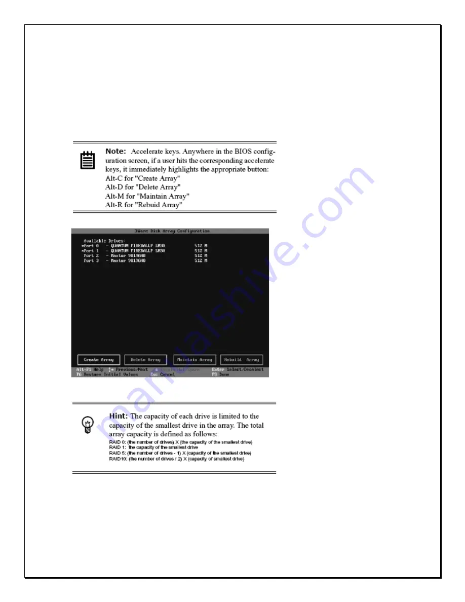
To create an array, first select the drives to be included by navigating the cursor 
over each drive and pressing 

Enter 

(see Figure C). An asterisk in the left most 

column indicates the drive is selected. You may include from two to eight drives 
in the array by selecting drives from the 

Available Drives 

section. To include 

drives that are part of an existing disk array you must first delete the array

.


Figure C. Selecting Drives for a Mirrored Array


Navigate to the 

Create Array 

button after selecting all the drives for the array. Hit 

Enter 

to bring up the 

Create Disk Array 

display (see Figure D and Figure E for 

examples). Check that the proper drives are listed. 


Summary of Contents for Pro 16/8

Page 1: ......

Page 2: ...tents The information contained in this document is subject to change without notice Edition First Edition March 11 2008 by NESS SECURITY PRODUCTS PTY LTD Copyright This publication contains information that is protected by copyright No part of it may be reproduced transmitted transcribed stored in a retrieval system or translated into any language without permission from the copyright holders Cop...

Page 3: ...ect sunlight 3 Do not use the Digital Video Recorder in a potentially flammable work area 4 Do not use your Digital Video Recorder on an unstable working surface This will prevent your Digital Video Recorder from falling or being knocked over and damaged 5 Do not store objects on the top of your Digital Video Recorder Do not exert pressure on the Digital Video Recorder 6 Do not use the Digital Vid...

Page 4: ...ot by the cords themselves This will prevent damage to the cords plugs ports and jacks 5 If an extension cord is used with this Digital Video Recorder make sure that the total ampere ratings of the products plugged into the extension cord do not exceed the extension cord s ampere rating Also make sure that the total current of all products plugged into the wall outlet does not exceed 15 amperes ...

Page 5: ...R 5 39 SCHEDULE RECORDING 39 CHAPTER 6 48 ACCOUNT SETTINGS 48 CHAPTER 7 52 SYSTEM SETTINGS 52 CHAPTER 8 62 ALARM SETTINGS 62 CHAPTER 9 72 ALARM LOG SCREEN NOTIFICATION 72 CHAPTER 10 74 USER LOG 74 CHAPTER 11 76 CONFIGURING GENERAL PURPOSE INPUTS OUTPUTS 76 CHAPTER 12 78 PAN TILT ZOOM 78 CHAPTER 13 84 PLAYBACK 84 CHAPTER 14 97 PRINTING 97 CHAPTER 15 102 REMOTE SURVEILLANCE 102 APPENDIX A 127 PRO 16...

Page 6: ...6 APPENDIX C 139 CONFIGURING ACTIVEX 139 APPENDIX D 141 ...

Page 7: ...peripherals and accessories to the DVR system please refer to Chapter 1 for the DVR system introduction A INSTALL HARD DISK 1 Pull out HDD Mobile Rack from PRO 16 8 RAID DVR System front panel 2 Install the Hard Disk SATA HDD to the Mobile Rack and locked it by screws of 6 32 L4mm ...

Page 8: ... 16 8 RAID DVR System 4 Power on PRO 16 8 RAID DVR System Press power button at the front panel to power on the DVR system Note The remain HDD capacity on DVR main screen appears 0 GB due to the DVR Raid Storage has not yet been made Raid Configuration ...

Page 9: ...he BIOS tool Power up or reboot your system Before the boot phase wait until you see a screen similar to Figure A Figure A BIOS Tool Press Alt 3 immediately to bring up the Disk Array Configuration display Exiting the BIOS tool To save your configuration modifications hit the F8 key After you have hit the F8 key to commit your changes a list of affected drives will be displayed and you will be ask...

Page 10: ...t spares Disk Arrays lists any existing arrays along with their member disks Figure B Disk Array Configuration Main Display RAID 1 Example Throughout the utility see Figure B use the Up and Down arrow keys to navigate Enter to select the disks or buttons and F1 for context sensitive help Toggle Hot Spare verbiage is black when the cursor is over a drive that can be specified as a hot spare and gra...

Page 11: ... from two to eight drives in the array by selecting drives from the Available Drives section To include drives that are part of an existing disk array you must first delete the array Figure C Selecting Drives for a Mirrored Array Navigate to the Create Array button after selecting all the drives for the array Hit Enter to bring up the Create Disk Array display see Figure D and Figure E for example...

Page 12: ...r RAID 1 duplicates or mirrors the data on both drives No data will be lost if one of the drives fails RAID 10 0 1 combines mirroring and striping providing both fault tolerance and high performance RAID 10 arrays require a minimum of four drives Configurations consist of 4 6 or 8 drives RAID 5 combines parity data and striping providing fault tolerance high capacity and high storage efficiency Th...

Page 13: ...s case you must disable the write cache To disable the write cache select disable from the array s Write Cache State selection The default for Write Cache State is enable Confirm array configuration Select the OK button to confirm creating the array or Cancel to reject it The array is not actually created and no data will be overwritten until you have finished making all your changes and select th...

Page 14: ... never initialized the initialization will then begin Any subsequent verify operations will then perform the verification of the array check data consistency An AEN will inform the user that the first verify is actually an initialization Specifying a Hot Spare The PRO 16 8 RAID DVR gives you the option to specify a hot spare from one of your Available Drives If a hot spare is specified and the arr...

Page 15: ... 24 fps frames per second And at a resolution of 320x240 for NTSC and 720x568 for PAL in True Color allows for comfortable uncluttered viewing The most powerful advantage is its built in RAID feature RAID 0 1 5 0 1 with redundant function to pretend data loss from HDD failure In addition PRO 16 8 RAID s amazing massive storage capacity with support 15 hot swappable HDDs to offer more than 6 months...

Page 16: ...e A Keyboard A Power Cord x 1 The User s Guide Do not throw the packaging materials away You may need them later to transport or ship the computer for repairs Opening the PRO 16 8 RAID DVR At the front of the Digital Video Recorder you will find the door covers the hard disk drive cage and connectors respectively Optional Devices To further enhance the utility of your Digital Video Recorder there ...

Page 17: ...ll reveal 10 hard disk drive bays Front Inside View Please refer to Figure 1 2 and the descriptions that follow to identify the components on the front side of the digital video recorder Figure 1 2 Front Inside View of the PRO 16 8 RAID DVR 1 Removable HDD Tray The fifteen metal HDD trays enable a secure fit for the HDD and the air ventilation holes in front ensure that air flows to the HDD thereb...

Page 18: ...e origin LED light indicates the HDD is being access The red LED light indicates the HDD Fail 5 Power button Press the button to turn on or off the Digital Video Recorder 6 USB port This is used to connect USB storage devices for the use of data export 7 Card Reader To connect the storage devices including Compact Flash Smart Media Memory Stick Secure Digital Multi Media IBM Micro Drive and PCMCIA...

Page 19: ...nect to a LAN or Internet 6 Printer Port This port is used to connect a printer to the DVR 7 PS 2 Keyboard Port This port connects a PS 2 compatible keyboard 8 PS 2 Mouse Port This port connects a PS 2 compatible mouse 9 COM 1 Port This port used for modem or speed dome 10 Power Supply and FAN Support auto Voltage Switch of 110 220V 11 Power Cord Socket This socket is used to connect the power cor...

Page 20: ... Digital Video Recorder for operation you should first connect all peripheral devices Make sure the digital video recorder is turned off before you do this Make sure the floppy drive does not contain a diskette if it does press the eject button to eject an inserted disk ...

Page 21: ...cameras to the BNC outputs at the back of the DVR 2 Connect a TFT LCD Monitor or CRT Monitor to the VGA Input 3 Connect a RJ 45 LAN cable to the Ethernet LAN Card 4 Connect a printer to the Printer Port 5 Connect a keyboard Mouse to their respective PS 2 Ports 6 Power cords differ from region to region Use the correct power cord based on your region 7 Check the Voltage Switch so that it matches yo...

Page 22: ...igure 2 3 You will automatically be able to see all cameras connected If a No Signal screen is displayed this means that the respective camera is not operating correctly please check all connections power supplies and the camera for the Video output fault Figure 2 2 The first viewable screen Main Screen ...

Page 23: ...wable screen shows the cameras connected and also gives users a first glance at the GUI Graphical User Interface The viewable screen takes up 75 of the screen while the controls are to the right of the viewable cameras ...

Page 24: ...ng this icon will display a Log on screen 5 Single View Icon Clicking this icon will place you in Single view mode 6 Quad View Icon Clicking this icon will display four camera images 7 9 Camera Viewable Icon Clicking this icon will display nine camera images 8 16 Camera Viewable Icon Clicking this icon will display sixteen camera images 9 Expandable Icon Clicking this icon will expand the viewable...

Page 25: ...Clicking this icon will remove the specified motion detection frame 4 Zoom in Icon Clicking this icon will zoom in on the selected camera 5 Zoom out Icon Clicking this icon will zoom out on the selected camera 6 Snapshot Icon Clicking this icon will take a single picture of the camera and save it into the database for printing 7 PTZ Icon Clicking this icon will allow users to view more icons that ...

Page 26: ...e Logon using administrative rights Creating users to access the DVR will be explained later under Creating Users However in order to enter the configuration panel and all other configuration settings you must perform the following Logging On 1 Step 1 Click the Logon Icon 2 Step 2 Under Username type in or select admin default under Password type in admin default Figure 2 5 Entering the default Us...

Page 27: ... versatile and easy to use Digital Recorder It is easy to Logon Logoff and Shutdown In order to shutdown the DVR follow these few steps 1 Step 1 Click the Logon Icon 2 Step 2 Click the Shutdown icon Figure 2 8 Shutting down the system After shutting down the system the product version number of the system will be shown on the top of right of the screen for example v3 1 2 ...

Page 28: ... the icons a sub note will appear explaining what that icon does Once you have started the Digital Video Recorder icons to the right of the main viewable area will give you access to different parts of the digital video recorder The following brief description explains how to enter those different screens Figure 3 1 The Main GUI Screen Settings Panel 1 Step 1 Click the settings icon on the right s...

Page 29: ...window is the Camera screen as shown above See the chapter on Configuring your much later in this manual Playback Panel 1 Step 1 Click the playback icon on the right side toolbar 2 Step 2 View the database of videos under the Playback Screen Click on a selected file and play the recorded data The red circle indicates the playback window video images ...

Page 30: ...og See the chapter on Viewing Playback images on your PRO 16 8 RAID DVR much later in this manual Single View Camera Screen 1 Step 1 Click the single view camera icon on the right side toolbar 2 Step 2 Select a camera from the main screen and click the Single View Camera mode The image will expand to single view mode As shown below Figure 3 4 The Single Camera View Screen ...

Page 31: ...y four camera viewpoints at 6 second intervals Figure 3 5 The Quad Camera View Screen Depending how your system is configured the DVR can be configured to display four separate cameras at 6 second intervals This can be configured in the main Settings Panel This will be covered later in this manual 9 Camera View Screen 1 Step 1 Click the 9 Camera view icon on the right side toolbar 2 Step 2 The scr...

Page 32: ...rvals This can be configured in the main Settings Panel This will be covered later in this manual 16 Camera View Screen only for PRO 16 2 DVR CD RW 4U 1 Step 1 Click the 16 Camera view icon on the right side toolbar 2 Step 2 The screen will display sixteen cameras in one screen Figure 3 7 The Sixteen Camera View Screen ...

Page 33: ...R in Full Screen Mode If the system has 16 cameras sixteen cameras will occupy the entire screen Figure 3 8 The Full Screen Camera View Screen Depending how your system is configured the PRO 16 8 RAID DVR can be configured to display one to sixteen cameras in Full Screen Mode This can be configured in the main Settings Panel This will be covered later in this manual ...

Page 34: ...n on screen set the background colours adjust the lighting of each camera set the image format and resolution change the image quality frame rate and adjust the motion detection zones Camera Settings To change each camera settings for the DVR follow these instructions 1 Click the Setup icon on the Main Screen 2 Click the diamond icon for the camera you want to configure 3 The small window under th...

Page 35: ... No Recording Motion Detection Recording Only ii Recording Continuous Fulltime Recording iii Scheduled Time Date Scheduled Recording Only Figure 4 3 Recording Selection Field Adding Colour for Text Text Background 4 Tick the Display Status checkbox to change the Text Colour and Background Colour i For Text Colour users can choose to have text in Black Red Green Blue White ii For Background Colour ...

Page 36: ...intensity iii Brightness Is the attribute of light source by which emitted light is ordered continuously from light to dark iv Contrast Is to compare or appraise in respect to differences While changes are made the camera image is automatically updated To return to previous settings click on Default Figure 4 5 Camera Colour Contrasting Setting Image Format Under Image Format selections i NTSC Thre...

Page 37: ...ere are four choices Low Medium High and Best Low produces highly compressed low image quality and Best offers high image quality Here you can select the quality and frame rate of each camera Figure 4 7 Recording Quality and Frame Rate FPS Frame Per Second ...

Page 38: ... camera scene just click hold and draw a frame sized window over the desired area for motion detection Repeat this and draw up to six individual zones into the camera scene to create effective detection zones Avoid nuisance false alarm objects such as busy roadways flickering TV VGA monitors shrubs trees and any object that is movable by drafts and wind or mechanical movement Click on Stop After y...

Page 39: ... capacity of your Digital Video Recorder Schedule your recordings according to your requirements Schedule Settings Once the PRO 16 8 RAID DVR is in record mode various scheduling times must be set for each camera according to the option chosen Follow these instructions to configure scheduling 1 Click on the Setup icon on the Main Screen 2 Click on the Schedule Tab Figure 5 1 Schedule Tab Window 3 ...

Page 40: ...Mode Selection Bar Once ii Daily Provides a recording option for Hours and Minutes Figure 5 3 Record Mode Selection Bar Daily iii Weekly Provides a recording option set date Sun through Sat and time for recording every week ...

Page 41: ...41 Figure 5 4 Weekly Schedule Settings iv Monthly Provides a recording option that allows users to set date and time for recording every month Figure 5 5 Monthly Schedule Settings ...

Page 42: ...ion will be shown in the schedule recording list 6 If you wish to delete a particular entry Select the entry and the Delete button 7 If you wish to modify a particular entry Select the entry and the Modify button 8 If you wish to delete all entries click the Del All button 9 Click Apply and OK to confirm your changes The screen will return to viewer mode ...

Page 43: ...benefit is to create individual times for different cameras giving users the freedom to choose activate cameras at different times This can be for PTZ Dome cameras and normal cameras 1 Select the Once option Figure 5 6 Selecting Record Mode 2 Select the number of the camera you wish to configure 3 Select the recording duration Figure 5 7 Duration Selection 4 Click Add The Once option Select camera...

Page 44: ...to set a particular period for recording each day 1 Select the Daily option Figure 5 8 Selecting Record Mode 2 Select the camera you wish to configure 3 Select the recording duration Figure 5 9 Duration Selection 4 Click Add The Daily option Select cameras ...

Page 45: ...ry week and then select a particular time for that date 1 Select the Weekly option Figure 5 10 Selecting Record Mode 2 Select the camera you wish to configure 3 Select the day of the week for recording 4 Select the recording duration Figure 5 11 Duration Selection 5 Click Add The Weekly option Select cameras ...

Page 46: ...ate for recording every month and then select a particular time for that date 1 Select the Monthly option Figure 5 12 Selecting Record Mode 2 Select the camera you wish to configure 3 Select the recording duration Figure 5 13 Duration Selection 4 Click Add The Monthly option Select cameras ...

Page 47: ...nd record option then click on the Modify button Deleting Schedule Settings Deleting recorded data will permanently delete information from the hard disk drive thus to free up disk space 1 Select the recorded scheduled period with care Figure 5 14 Delete Schedule Settings 2 Click the delete button To Delete All 3 Click the Del all icon ...

Page 48: ...al user does not have supervisory powers and is limited to certain user ability of the PRO 16 8 RAID DVR system The administrator of the PRO 16 8 RAID DVR system can give users local remote access and can allow users only to access certain cameras Follow these few steps to create and configure user access to the PRO 16 8 RAID DVR system 1 Click on the Setup icon on the Main Screen 2 Click on the A...

Page 49: ...Type field to reconfirm Figure 6 2 Name Password Confirmation Field 5 Click the checkbox next to Enable to select the user s type and authority 6 Select Supervisor to give a user total control over the DVR or Normal to limit the user s access Click Enter the name of the user followed by a Specified password ...

Page 50: ... to change their username and password through a browser over the LAN or Internet 11 Select Allow config from remote to enable users to change their system configuration through a browser over the LAN or Internet 12 Click Allow Playback to enable users to playback the recording files 13 Click Allow Control PTZ to enable users to control PTZ cameras 14 Select a checkbox to mark a given camera as av...

Page 51: ...51 3 Click Modify button 4 Click Apply then OK to confirm changes Figure 6 5 Modifying User Settings To Delete Users 1 Select the user 2 Click delete 3 Click Apply then OK to confirm the changes ...

Page 52: ...ttings will ensure that the DVR system may be correctly viewed both locally and remotely Incorrect system configuration may result in abnormal operation and could make tech support more complex and time consuming Follow these steps to set up your DVR 1 Click the Setup icon on the Main Screen 2 Click the System Tab Figure 7 1 System Menu ...

Page 53: ...for the purpose of machine identification when sending an email alarm 4 Enter an IP address Subnet Mask and depress the LAN diamond to activate the Default Router Type in the Default Router Gateway that your Administrator assigned you 5 Click Apply and OK ...

Page 54: ...lick the Dial button to test the dial up procedure If it is successful the Disconnect field will revert to the IP assigned by ISP This will be finished when the connection is idle for 30 seconds the connection will then be disconnected by the system automatically and the IP field will revert to Disconnect 3 If the DVR will use a dialup modem for e mail delivery the Network connection would disconn...

Page 55: ...ety of user selectable back up devices CD RW or Memory Card 1 Click on Backup Config 2 The list of back up device selection to Export will be displayed Figure 7 3 Back up devices selection 3 Select the desired back up device 4 Click OK Restoring settings from the Back up device The DVR system can restore the system configuration settings from the back up device The system supports different user s...

Page 56: ...hen the hard disk drive is full an alarm will be triggered indicating that the system disk is full However if the system has Recycle Rec enabled the system will continue to record over old video data thus replacing previously recorded data 1 Click the System Tab 2 Under Others click the checkbox next to Recycle Rec Figure 7 6 Recycle Rec 3 Click Apply then OK to activate the changes Auto Login A s...

Page 57: ...ll automatically show different cameras at six second intervals 1 Click the System Tab 2 Under Others click the checkbox next to Cam Auto Switch 3 Click Apply then OK to activate the operation Figure 7 8 Cam Auto Switch Settings Minimize Video Size Minimizing the video size allows the DVR System to save more hard disk space but the system performance will likely be somewhat degraded due to additio...

Page 58: ...rame rather than an entire new frame The greater the number of P frames after each I frame the more space will be saved on the hard disk but the more computation will be needed to uncompress the video for playback To use this setting 1 Click the system settings tab 2 Under the Others item adjust the Number P Frames after I Frame setting 29 is the default setting 3 Click Apply then OK to apply the ...

Page 59: ...Frame setting values range from 0 60 Enable telnet The Enable telnet setting refers to start or stop the telnet domain The default setting allow user to login DVR system from remote site using telnet utility for maintenance For security consideration user can disable this function as following 1 click the System tab 2 under the Others item uncheck the Enable telnet 3 Click Apply then OK to apply t...

Page 60: ...e network server the ftp server the e mail server that should be used through Internet connections or there are several DVR hosts providing service outwards then a Virtual Server should be an ideal solution Virtual Server allows multiple applications to share one legal IP by assigning various application requirements respectively to the internal virtual IP of the company Basically functions and se...

Page 61: ...ask 255 255 255 DNS Server 192 168 1 2 Default Router 192 168 1 1 Virtual Server IP 211 23 141 2 With the above settings complete connect through a browser to http 211 23 141 2 this will connect to the Host with the virtual IP address http 192 168 1 3 Figure 7 14 Virtual Server Port Settings ...

Page 62: ...mera can be configured under the first screen Cam However users may not be aware when motion detection is triggered Therefore under Alarms periods of time can be setup so as to trigger an alarm when motion is sensed There are four areas of configuration General Camera Enable Trigger Period and Alarm Triggering Device 1 Click the Alarm Tab 2 The first Field General refers to setting the interval ti...

Page 63: ...63 Figure 8 3 Trigger Period Field 2 Then select one of the Triggering Devices from the tab windows below Figure 8 5 Tab Window Selection Alarm Record Triggering ...

Page 64: ...neral select the Duration for motion detection triggering and click the checkbox next to Motion Rec See Figure 8 5 to select the frame speed for motion detection Figure 8 5 General Field 3 Select the Camera to configure Figure 8 6 Camera Settings 4 Select the first Enable field for 24 hour recording reaction or select the Trigger Period Enable field for record duration only and set the record dura...

Page 65: ...larm Sounds 1 Click the Alarm Tab first 2 Select the Camera 3 Tick off the entire Enable field first then select Enable under Trigger Period 4 Click the Sound Tab Figure 8 8 Sound Tab 5 Click on the Select button to choose an alarm sound from the sound list window Figure 8 9 Sound Selection Window ...

Page 66: ...ack of sound 8 Then click Add 9 Click Apply and OK Alarm Message triggering Alarm Pop Up Screen Messages when enabled will show a message on GUI at the time of detecting alarm and details of the alarm Follow the instructions below to set Alarm Message 1 Click the Alarm Tab 2 Select the Camera see Figure 8 6 3 Select a Trigger Period see Figure 8 7 4 Click the Message Tab ...

Page 67: ... and Motion Detection is enabled on that particular camera a pop up screen will appear as below to warn users that the DVR has detected motion Figure 8 12 Message pop up warning 7 The users may click the OK button 8 To Delete this function click the Del button 9 Users will be prompted to confirm Click OK Figure 8 13 Message Confirming Window ...

Page 68: ...eriod see Figure 8 7 4 Click the Email Tab Figure 8 14 Email Tab 5 Setup the email address to Mail to and cc set up Send x secs video for the seconds of video to be attached and sent In addition enable the icon in front of the Attach playback program to send the video playback decoder program 6 Then click Add Apply and OK IMPORTANT please ensure all Internet and Email servers are functional and en...

Page 69: ...w many seconds you d like to delay before the Alarm Voice is sent and 1 to 10 seconds may be sent see picture below 5 Repeat Times is used to set the times you d like to trigger the alarm and 1 to 10 times can be set see picture below Figure 8 15 Voice Tab 6 Then click Add the window below will show Voice with the selections made 7 Click Apply and OK Alarm Fax Triggering Modem required Alarm Fax w...

Page 70: ... Add the window below will show Fax with the selections made 8 Click Apply and OK Alarm Relay Output Triggering Alarm Relay Output activate the relay output port at the time of detecting the alarm Follow these instructions to set the Output Port 1 Click the Alarm Tab 2 Select the Camera see Figure 8 6 3 Select a Trigger Period see Figure 8 7 4 Click the Output Port Tab ...

Page 71: ...delay time may be set from 0 to 999 seconds 8 Under the Active Duration there are 0 to 999 seconds to choose The setting of 0 second means permanent triggering 9 Then click Add the window below will show Output Port with the selections made 10 Click Apply and OK Tick off to Enable Disable The Delay Trigger The Active Duration Note An external standard 56K modem is required to transmit alarm pager ...

Page 72: ...ameras set off the alarm at what time the alarm was triggered and provides a description of what happened The log is simple and allows the administrator only two options a to delete a single log b to delete all log files Follow the next few steps to achieve this Deleting a Log 1 Click the Alarm Log Tab Figure 9 1 Alarm Log 2 Select the file you wish to delete Figure 9 2 Selection File 3 Click dele...

Page 73: ...task Deleting all Logs 1 Click the Alarm Log Tab Figure 9 4 Alarm Log 2 Click Del all 3 A confirmation pop up screen will appear asking to reconfirm see Figure 9 5 below Figure 9 5 Confirmation Window 4 Click Confirm to continue or Cancel to restart 5 Click Apply then OK to complete the task ...

Page 74: ... is only a log and the information cannot be cleared or changed Information in this log can only be deleted or the entire log file can be deleted Follow these few steps to delete files Deleting a Log 1 Click the User Log Tab Figure 10 1 User Log 2 Select the file you wish to delete Figure 10 2 Selection File 3 Click Del 4 A confirmation pop up screen will appear asking to reconfirm see Figure 10 3...

Page 75: ...0 4 User Log 2 Click Del all 3 A confirmation pop up screen will appear asking to reconfirm see Figure 10 5 below Figure 10 5 Confirmation Window 4 Click Confirm to continue or Cancel to restart 5 Click Apply then OK to complete the task ...

Page 76: ...PIO provides connections to multiple Alarm Inputs and Dry contact closure Outputs All models come standard fitted with a 4 in out alarm I O Optional I O ports can be added to max 16 in out module making system integration easy and fuss free Figure 11 1 GPIO Window ...

Page 77: ...ration requirements Individual delay timer periods can be set so that the interval time of the DVR alarm inputs can be started when the sensors are triggered Figure 11 2 DI Field Output Settings The DVR is able to provide 16 relay outputs for external sensor connections and can be set to active ON or active OFF Application requirements The GPIO ports are optional products Figure 11 3 DO Field ...

Page 78: ...sult your dealer for more information on how best to configure your system with leading PTZ camera providers This chapter shows users how to configure a PTZ camera that is compatible with the PRO 16 8 RAID DVR Let s take a look at the PTZ window in more detail Click the PTZ Tab Figure 12 1 PTZ Tab On the left side of the window you will see a live view from your PTZ camera This allows you to confi...

Page 79: ... list next to Speed Users can set the speed range from 1 8 If you are not familiar with this system or using a PTZ camera please consult your dealer for advice Focus When connecting a PTZ camera to your PRO 16 8 RAID digital video recorder you have the option to focus in on the picture Use to focus in to focus out and to have the camera be automatically adjusted Zoom When connecting a PTZ camera t...

Page 80: ...r each preset function users can adjust the speed and time of the camera 1 Click the Preset to set the serial number from 0 to 128 0 means NULL that is NO MOTION 2 Set the Speed of the PTZ camera range from 0 to 7 and then adjust the Dome direction Figure 12 4 Dome Speed controller 3 Using the icons to Focus in Focus out or Auto focus the lens Figure 12 5 Focus Controller 4 Zoom in Zoom out to adj...

Page 81: ...ouping Preset The PRO 16 8 RAID Digital Video Recorder gives users the option to set up to 128 presets Of the 128 presets preset 1 to 4 make up Group one preset 5 to 8 make up Group Two preset 9 to 12 make up Group Three and preset 13 to 16 make up Group Four The rest presets are only used to view pictures on particular directions conveniently The main purpose of Group preset is to use all presets...

Page 82: ...omatically in the mode of Auto Pan Setting Group 1 and Group 2 Choose Group 1 and Group 2 and click Set Group button Function To operate presets 1 to 8 in the mode of Auto Pan Setting Group 1 Group 2 and Group 3 Choose Group 1 Group 2 and Group 3 then click Set Group button Function To operate presets 1 to 12 in the mode of Auto Pan Setting Group 2 Group 3 and Group 4 Choose Group 2 Group 3 and Gr...

Page 83: ...om the following icon CD 55 Min King CD 55H Min King CD 56 Min King CD65 Min King Lilin DynaColor Hsintek MD Nicecam Megasys Neon Neno T Pelco D Star Note Different Speed Dome models have different functionality please refer to the user guide of the Speed Dome you wish to connect ...

Page 84: ...wind All these features are covered later in this chapter Lets first take a look at how we can review playback To view Playback click the playback icon A pop up database will appear giving you the choice of selecting a file selecting the date searching or by checking the list At the bottom of the screen you will notice a set of icons These icons will help later when using the playback image Bottom...

Page 85: ...ra Search Select the camera you want to view playback images 4 Search Button Click the search button to search for a file 5 List Button Click this button to display a list of the recorded database 6 Open Click here to view a file 7 Cancel Button Cancel any action 8 Reset Button Click this button to reset any functions Understanding the Bottom Toolbar The Bottom Toolbar appears only when you click ...

Page 86: ...us image Click this icon to rewind play Click this icon to pause play Click this icon to play the file Click this icon to slow forward the clip press once to go forward in speed of 1 2 press twice in speed of 1 4 press three times in speed of 1 6 Click this icon to fast forward the clip and the optional speeds are 1x 2x 4x 6x 8x and 10x Press once to play at the speed of 2x press twice at speed of...

Page 87: ...on Bottom Toolbar Figure 13 4 Playback Screen 2 Select a date and time from the calendar Figure 13 5 Calendar Camera Selection 3 Select a camera 4 Click Search List to show all the clips 5 Then the recorded database will be listed on the screen if the camera is defined with a name the name will appear in the field of Description Pop up Database ...

Page 88: ... Camera Database 6 Choose the recorded clip to play Figure 13 7 Camera Selection 7 Double click the selection or click Open The selected file will appear in front of the Main Screen Figure 13 8 Recorded playback data ...

Page 89: ...lbar 9 Double click the image to enlarge Figure 13 9 Enlarged Image 10 Double click the image again to enlarge Figure 13 10 Full size Playback image 11 To reduce the size or go back to the original size just click the right mouse button ...

Page 90: ...back from a connected media device with saved data USB HDD or USB handy drive Memory Stick Please note that the USB device should be connected to DVR before powering on Neighbor Playback recorded data stored on a server hard drive through a Network connection LAN WAN Direct connect Floppy FDD Playback recorded data from a floppy drive CDROM Playback recorded data from the external USB CD RW ...

Page 91: ... A database of alarm triggered playback files will appear Alarm Log Figure 13 11 Alarm Log Please select the file you want from the alarm video log Double click it Or click Open The selected clip will appear on the Main screen Click play to view the clip Figure 13 12 Alarm Triggered File ...

Page 92: ...3 Tag field 2 Type in the Tag name first 3 Click Insert button the information about the camera Tag time Description the camera name will be added to the system automatically and then be listed Figure 13 14 Tagged frame 4 The particular clip is then saved and can be searched and viewed for later reference by means of tag And the camera number and the time is in sync with the tag 5 Then a mark will...

Page 93: ...his icon The following image will appear Figure 13 16 Export image 2 The image highlights the hours minutes and seconds Use the drop down list to select the time frame you would like to export Click Next to continue 3 The DVR then asks you to choose the media and the place you d like to export the clip to and the name of the clip Once complete click OK to confirm ...

Page 94: ... image more clearly Figure 13 18 Sharpen Image Open the recorded image Click on this icon to blur the image Click on this icon to sharpen the image The blur Icon and the Sharpen Icon is at the same position only one of them will appear at the same time When Blur Icon appears you can use it to blur the image while Sharpen Icon appears you can use it to sharpen the image ...

Page 95: ... or background screen may be unclear The directional icons can be used to move each playback video to different parts of the screen Click on the separate directions to position your video in the right place See the images below that demonstrate this function Figure 13 20 Viewing more than one playback clip ...

Page 96: ...96 Figure 13 21 More than one playback image ...

Page 97: ...your monitor The PRO 16 8 RAID DVR accepts many forms of printers Please consult your dealer to see what printers are compatible with the PRO 16 8 RAID DVR Configuring your Printer Follow these few easy steps to setup print function 1 Click the Setup icon on the Main Screen 2 Click the System Tab Figure 14 1 System Tab 3 Click the Printer Setup icon 4 The next screen will give a list of printers t...

Page 98: ...et the size of paper and Resolution to set the resolution and then Colour depth Unprint Mode to set the colours for colour printers 6 Click OK 7 A pop up screen will appear prompting you to print a test page Figure 14 3 Printer Test Page 8 Click Confirm to continue View your printed material ...

Page 99: ...searching or by checking the list At the bottom of the screen you will notice a set of icons These icons will help later when using the playback image Pop up Database Bottom Toolbar Figure 14 4 The Playback Screen 2 Select a date and time from the calendar Figure 14 5 Calendar Camera Selection 3 Select a camera 4 Click Search List or Open ...

Page 100: ... that camera will open Figure 14 6 Camera Database 6 Select the date and time to view the clip Figure 14 7 Camera Selection 7 Double click the selection or click Open The selected clip will appear in front of the Main Screen ...

Page 101: ... new window will appear to show the image that has been taken Before taking a snapshot press the pause button to freeze the picture 10 Click the Export from the Bottom Toolbar to print the image 11 If the print is successful a new window will appear to give you a notice Click Confirm to view the printed data ...

Page 102: ...like the PRO SERIES DVR All functions available on the local system can be operated from a browser remotely Once you have setup the local LAN and Internet functionality from the System Window you are able to easily and conveniently view material from your digital video recorder remotely Let s take a closer look at what happens when you want to view data remotely 1 Click on the Configuration icon f...

Page 103: ... 2 Browser IE 5 In the address field enter the IP address 6 Hit Enter The remote window will appear Figure 15 3 Browser Window 7 Under Name enter admin 8 Under Password enter admin The default password 9 Click Login ...

Page 104: ...t Monitor Click this area to preview still images and monitoring live images and video Playback Click this area to view playback recorded data Setup This part has 8 kinds of remote setting functions Camera Schedule Account System Alarm Alarm Log User Log and GPIO Logout Click this area to close all operations and return to the DVR remote login screen Lets go over each section one by one in more de...

Page 105: ...onitoring Each camera view has a checkbox with the cameras name or identification depending on how you configured the local machine 2 Click the Clean All link to view disable all camera connections 3 Click the checkbox next to a particular camera to view a live feed 4 Click Monitor to view that particular camera 5 Click as many checkboxes as you wish or as many cameras that are connected to your m...

Page 106: ...106 Single Remote View Figure 15 6 Single Remote View Quad Remote View Figure 15 7 Quad Remote View ...

Page 107: ... 9 12 Camera Remote View Depending on the speed of your LAN or Internet connection the viewing quality will change Faster connections means better viewing capability Configuring Setup Remotely The functions for setup remotely are exactly the same as they are locally Lets take a closer look ...

Page 108: ...ra Configuration Screen All remote functionality is similarly setup as the local machine The only difference is the way the interface looks On the left side of the main viewing area are the links to all the setup functions Clicking on each of them will link you to the respective functions Select a camera and various other parameters from the drop down list Setup Link ...

Page 109: ...s Figure 15 12 Remote Schedule Screen The remote schedule screen is divided into various parts for easy configuration Select the recording mode and cameras to start the configuration Figure 15 13 Remote Scheduling 4 Select the date icon A pop up calendar will appear ...

Page 110: ...110 Figure 15 14 Remote Calendar scheduling 5 Click Add to activate the settings Once you have completed all schedule settings you can view a log of all changes Figure 15 15 Remote Schedule Log ...

Page 111: ... Click the data you wish to modify Figure 15 16 Remote Modify Window 2 Click the Modify icon Figure 15 17 Remote Modify Parameters 3 View the modifications Figure 15 18 Modifying a Schedule remotely Click on the data intended to modify ...

Page 112: ...les the administrator to make changes to the PRO SERIES DVR without the need to visit the DVR 1 Click the Account Settings link on the browser The administrator will see the main remote account screen Figure 15 19 Remote Account Settings Screen 2 Click Add to add a user The screen below shows how a new user has been added with his her respective rights ...

Page 113: ...113 Figure 15 20 Adding users remotely The same ease of use can be done with other functions ...

Page 114: ...r you do not have to change the IP address functions on this screen If these changes are made you will lose the connection One of the changes made to the main local setup screen is the fact that here you are able to backup data to an external device If you are using backup storage and you intend to backup data on your digital video recorder please consult your dealer on how to use this function ...

Page 115: ...rs the opportunity to change alarm functions from a remote site Figure 15 22 Remote Alarm Settings Once you have made the selective choices available under Remote Alarm settings click OK to make the changes effective Figure 15 23 Remote Alarm verification ...

Page 116: ...te all alarm logs Click on the Alarm Log link You will see the screen below Figure 15 24 Remote Alarm Log If you would like to delete all logs click in the checkbox next to Select All To delete individual logs click next to the checkbox of the file you want to delete and click the Delete icon ...

Page 117: ...sers accessing the machine Click the Login Log link to view the user log remotely Figure 15 25 Remote User Log If you would like to delete all logs click in the checkbox next to Select All To delete individual logs click next to the checkbox of the file you want to delete and click the Delete icon The next step is to view all playback material remotely ...

Page 118: ...Main Screen Figure 15 26 The Remote Playback Link Understanding the Playback Side Toolbar The playback sidebar gives users many choices These choices give users the freedom to manipulate the image to their benefit Lets take a closer look ...

Page 119: ...ext frame 9 Snapshot Button Click this button to take a snapshot and print it out 10 Export Button Click this button to export and save an image to disk 11 Tag Button Click this button to find a tagged image or file 12 Speed Drop Down List Click this list to change the viewing speed 13 Zoom Out Button Click this button to zoom in and out of the image The very next screen puts you in playback mode ...

Page 120: ...s of each video screen You may fast forward at 2 4 6 8 or 10 times speed Slow forwarding at 1 2 1 4 1 6 1 8 or 1 10 times speed There is a horizontal scroll bar on the top of the playing window which facilitates the user to fast search films You may press and hold the left mouse button on it and drag it from left to right Once you have found your searched video image click the Play button at the r...

Page 121: ...ll appear 1 Select the camera and the time you wish to preview 2 Click the search button to list all recorded data for that particular time frame Figure 15 29 Playback by File Move the mouse to the file you want to play and double click the file to play it Figure 15 30 File Selection Once you have clicked the file a frame will appear showing the selected image ...

Page 122: ...22 Figure 15 31 Remote Playback image When you want to see the image enlarged just click the Zoom In button and then the image will be enlarged See image below Figure 15 32 Remote Playback Enlarged Image ...

Page 123: ...ould like to take snapshots of video and print it out In order to do this 1 Click the Snapshot button 2 From the pop up window select the resolution size of your print The system provides three resolutions 320x240 480x320 and 640x480 Figure 15 33 Snapshot Resolution 3 Choose the resolution and click Print You will be prompted to select a printer Press the Print button ...

Page 124: ...rting an image allows users to access images from the hard disk and save it onto your local hard drive 1 Click the Export button 2 Select an exporting duration Figure 15 35 Export Duration 3 Click Save this file to disk and click OK Figure 15 36 Save to disk 4 Choose the location and click save ...

Page 125: ...n the future To create a tag 1 Click the Tag button on the playback side toolbar 2 The Tag pop up window will appear asking for a tag name Figure 15 38 Tag Name Field 3 Insert a Tag name 4 Click on the Playback Side Toolbar and click Tag File Figure 15 39 Tag File List 5 Select the file you wish to view 6 Click Open to view the image or delete to discard the file ...

Page 126: ...VR host Once you have added all the GPIO modes click OK in the right corner to save the changes to the DVR Host and make them effective Figure 15 41 Remote GPIO Screen After completing all the settings or after using this function click Main to use other remote functions Or you can click Log out to leave remote monitoring system ...

Page 127: ...to use Backup to NAS NTP and Multi Playback functions of your DVR you must purchase and install one KEYPROBE from your vendor this is optional Connect the optional KEYPROBE with the print port The printer port remains operational and can be connected to a printer ...

Page 128: ...on file data the demand on storage space will be higher NAS can support IP network protocols therefore users can backup their DVR data to NAS through Internet LAN at anytime Steps 1 Click the Setup icon on the main screen 2 Click the System tab 3 Click the NAS button to popup the NAS Setup windows ...

Page 129: ...nable it Once overwrite is enabled NAS will initiate deleting files The deletion will be based on the free space lesser or equal to the Lower band This procedure will be continued until the free space is more or equal to the Upper band 9 Backup Period DVR will not continuously archive data to NAS the Backup Period is the time interval to make ensure NAS synchronized with the DVR and backup new dat...

Page 130: ... The Network Time Protocol NTP is used to synchronize the clock of a DVR to another reference time source Steps 1 Click the Setup icon on the main screen 2 Click the System tab 3 Click the NTP button to popup the NTP setup windows ...

Page 131: ...tivate the selected NTP server 7 Delete Delete the selected NTP server in the list 8 Enable Clicking the Enable checkbox enables time interval updates to the DVR every hour day week or month as nominated Note The DVR will only connect to the top first highlighted NTP server within the list and if the connection fails the DVR will connect to the next one and so on 9 Time Adjust manually adjusts the...

Page 132: ...n screen and then click multi playback you ll see the Multi Playback windows as below 2 Click to select the playback clips according to cameras and date time 3 Click the slice4 slice9 or slice16 to select 4 camera 9 camera or 16 camera synchronous multi playback respectively 4 Click OK and then click the icon to playback ...

Page 133: ...133 5 You can use Hour and Minute to change the start playback time Example Click the hour the playback time will be changed from 14 00 to 15 00 6 You can click any camera view to zoom the image ...

Page 134: ... properly connected to their respective ports Ensure that none of the connectors pins are bent or broken Check all cables connected to the Digital Video Recorder If any are cut frayed or damaged in any way replace them right away Never use a damaged cable A damaged cable is not only a fire hazard it may also cause a short circuit resulting in irreparable damage to the Digital Video Recorder Isolat...

Page 135: ...e the Digital Video Recorder s cable with another cable from a different type of device even if the cables look exactly the same The wiring inside the cables may be different The Power On Self Test The Power On Self Test POST runs every time you turn on or reset the Digital Video Recorder The POST checks memory the main system board the display the mouse the disk drives and other installed options...

Page 136: ...splay keyboard or mouse an error message is displayed on the screen and testing is stopped It is important to remember that the POST does not test all areas of the Digital Video Recorder only those that allow it to be operational enough to run diagnostic programs If your system does not successfully complete the POST but displays a blank screen emits a series of beeps or displays an error code con...

Page 137: ...lem persists after trying all of these suggestions turn off the digital video recorder and consult your dealer or a qualified service technician Problem Solution The Digital Video Recorder keeps making a beeping noise at regular intervals When the Digital Video Recorder is low on hard disk drive capacity it emits an audible warning signal Turn off the Digital Video Recorder and replace the hard dr...

Page 138: ...er Your dealer can determine if the problem is something that requires the Digital Video Recorder to be taken to the dealer Before you call your dealer however prepare the following information How is your Digital Video Recorder configured Your dealer needs to know what peripheral devices you are using What messages if any are on the screen What have you done already to try to solve the problem If...

Page 139: ...s The relative settings about the security of ActiveX can be configured in the way below Click the Tool Icon under MS Internet Explore to select Internet choices Click Security Tab Method 1 Lower the Security Level of Internet Lowering the level is only required during setup do not leave in this lowest setting Figure b 1 Security Tab Method 2 Set to be Trusted Sites Only trusted sites authority of...

Page 140: ...re b 2 Creditable Website Tab 2 Click Sites Icon Figure b 2 Creditable Website Tab 3 Add this website to this field 4 Cancel the selection of Require server verification https for all sites in this zone 5 Click Add then OK to complete the setting ...

Page 141: ...ne year warranty from the date of purchase against defects in materials or workmanship when the PRO 16 8 RAID DVR is installed and operated in accordance with the instructions provided in this user s manual and is in normal use ...

Page 142: ...LD 4170 Ph 07 3399 4910 Fax 07 3217 9711 nessbris ness com au WA Unit 1 567 Newcastle Street West Perth WA 6005 Ph 08 9328 2511 Fax 08 9227 7073 nessper ness com au Copyright Notice All rights reserved No part of this publication may be reproduced transmitted or stored in a retrieval system in any form or by any means electronic mechanical photocopying recording or otherwise without the prior writ...

Reviews: