NESS - M1 Installation and Programming Manual
Page 13
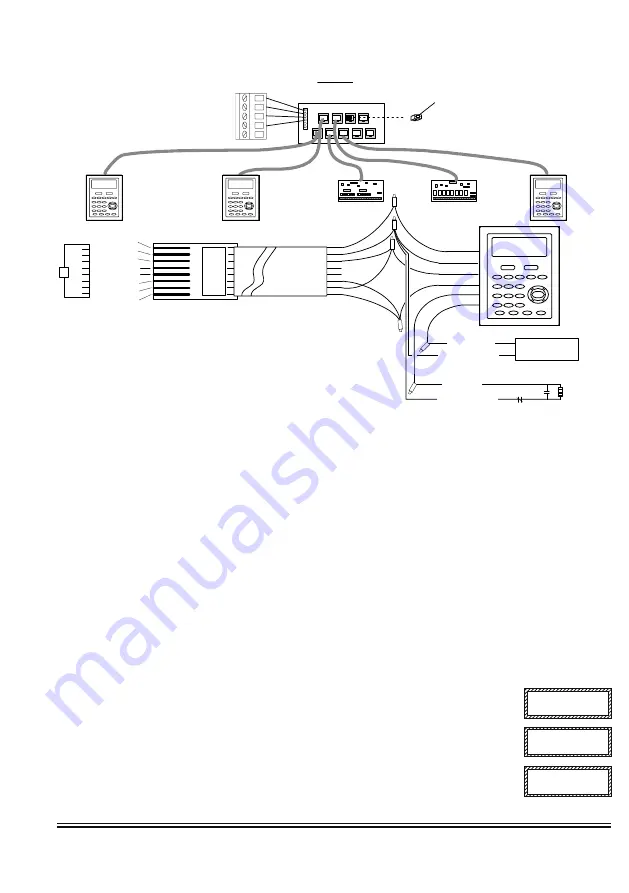
The ideal way to connect multiple home run cables is with an ELK-M1DBH Data Bus Hub. It accepts CAT5 or CAT6 cable with RJ45 plugs on the ends. It
does all the work of series connecting the DATA lines A & B. Terminate at the hub using the included RJ45 Terminating Plug in the first unused jack.
8 - Brn/Wht
7 - Wht/Brn
6 - Org/Wht
5 - Wht/Blue
4 - Blue/Wht
3 - Wht/Org
2 - Grn/Wht
1 - Wht/Grn
RED +12V
BLACK (-)
GREEN (A)
WHITE (B)
BROWN
Pin1
RJ45 Plug
A
G
rn
/W
ht
A1
Org/
Wht
-
W
ht/
Brn
+
B
rn
/W
ht
B1
W
ht/O
rg
B
Wht/G
rn
Spare
Spare
ELK-M1DBH Data Bus Hub
CAT5 or
CAT6 Cable
COLOR CODE
for CAT5 or CAT6 Data Bus Cable to ELK-M1DBH Data Bus Hub.
Pin1
Mount M1DBH inside control.
Connect it to the M1 Data Bus
terminals using a 4 conductor cable.
J2
J4
J6
J8
J1
J3
J5
J7
J9
RJ45 Terminating Plug
Insert in first unused jack and
terminate the control at JP3.
DO NOT TERMINATE AT
ANY OF THE DEVICES!
CAT5 Cables
Fro
nt
vie
w
Daisy Chain Connection of Data Bus Devices
Using ELK-M1DBH And CAT5 Cables.
RS-485 DATA BUS
Optional programmable Zone Input from Keypad
Optional programmable Output from Keypad
Load (50mA max)
I.E. LED, Relay
-
+
To BLACK (Neg) Wire
To BROWN Wire
N.C. N.O.
2200
Ohm
EOL
To BLACK (Neg) Wire
To BLUE Wire
BLUE
Setting the Data Bus Address and Enrolling Device(s) into the System
Keypads and expander devices communicate with the M1 over the RS-485 4-wire data bus. Each device must have a unique
address setting (from 1 to 16) within it's device type. Keypads are device TYPE 1, input (zone) expanders TYPE 2, output
expanders TYPE 3, etc. The purpose of device types is so that the address numbers can be re-used in each different device
type. It is OK to have a Keypad, a Zone Expander, and a Output Expander all set to address 2 and on the same data bus since
each device is a different device type.
It is NOT OK to have duplications of addresses within the same device type. I.E.
Multiple keypads on the same control cannot be set to 'like' addresses.
ADDRESS:
From the factory all keypads are set to address 1. Valid keypad addresses are 1 to 4 for the ELK-M1, or 1 to 16 for
the ELK-M1G. The first keypad on the system (Keypad 1) is automatically enrolled upon power up. Each additional keypad must
be assigned a unique address and then manually enrolled from “Menu 1 - Bus Module Enrollment”. (See M1 Instruction
Manual, Menu 01, for complete instructions on Bus Module Enrollment)
1. Press and hold the " * " key, followed by the F5 key . HOLD BOTH keys pressed for 5-10 seconds or until the LCD displays:
Exit when done. F1 Set Addr.
(This is Keypad setup mode)
NOTE: This mode may also be accessed by removing power from the keypad (unplugging the data bus cable) and then
applying power while holding any key pressed.
2. Press the F1 key to display the current address setting.
3. Set the desired address by entering a number from 1 to X.
4. Press the Exit key when done.
Auth. Required
Enter Valid Pin
01-Bus Module
Enrollment
ENROLLING:
1. Press the ELK key, then press 9 (or scroll up) to display 9 - Installation Programming. Press the
RIGHT arrow key to select this menu. The Installer Program Code (PIN) must be entered to access
this menu.
2. Enter the Installer Program Code. (See M1 Manual for the default Code)
3. The first Installer Programming menu displayed will be "Bus Module Enrollment"
4. Press the RIGHT arrow key to select this menu. "Enrolling Bus Modules" will display
5. The M1 transmit an enrollment message to all data bus devices, following by a display showing the
total Bus Modules that are enrolled. To view the enrolled devices and/or remove a device press the
RIGHT arrow key next to the word Edit.
6. Press the * or Exit keys to exit Installer Programming.
XX Bus Modules
Enrolled, Edit
r


