IMO-240 EN - Issue 7/2020
4
3.2 INSTALLING IN THE PIPELINE
WARNING:
THE VALVE SHOULD BE TIGHTENED BETWEEN
FLANGES USING GASKETS AND FASTENERS
COMPATIBLE WITH THE APPLICATION, AND IN
COMPLIANCE WITH APPLICABLE PIPING CODES
AND STANDARDS. CENTER THE VALVE AND FLANGE
GASKETS CAREFULLY BETWEEN FLANGES. DO NOT
ATTEMPT TO CORRECT PIPELINE MISALIGNMENT BY
MEANS OF FLANGE BOLTING!
The valve may be installed in any position and offers tight
shut-off in either flow direction. When in a horizontal line, it is not
recommended to install a valve with the stem on the underneath
side as debris in the pipeline may enter the body cavity and damage
the gland packing.
Refer to Section 4,
MAINTENANCE
for stem seal adjustment. If
there is seepage past the stem seal upon installation, it means
the valve may have been subject to wide temperature variations in
shipment. Leak-tight performance will be restored by a simple stem
seal adjustment described in the
MAINTENANCE
section.
3.3 VALVE INSULATION
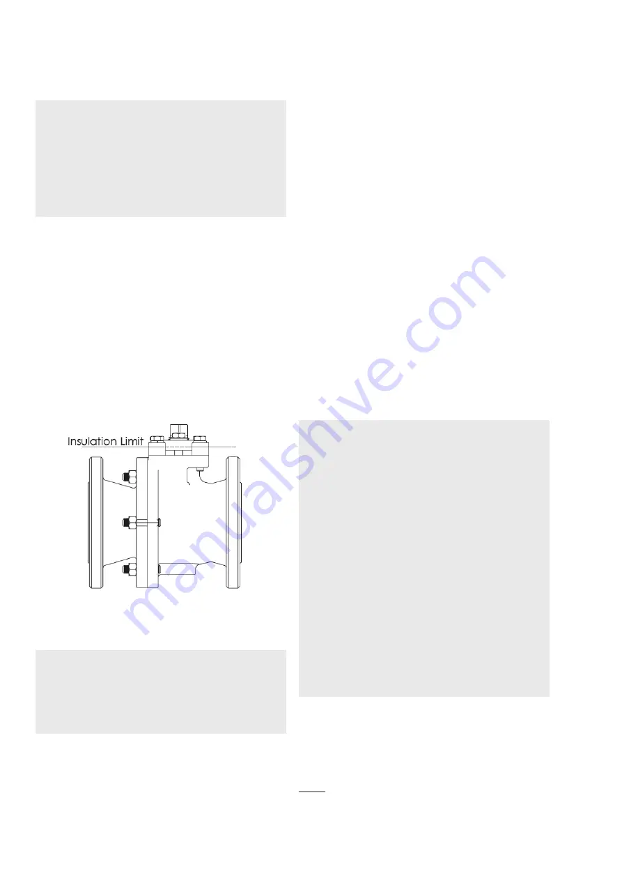
Easyflow by Neles™ ball valves do not require insulation. If desired,
the valve may be insulated; however, the insulation must not continue
above the upper level of the valve. See
Figure 2.
Figure 2.
Insulation of the valve
3.4 ACTUATOR
WARNING:
WHEN INSTALLING THE ACTUATOR ON THE
VALVE, MAKE SURE THAT THE VALVE ASSEMBLY
FUNCTIONS PROPERLY. INFORMATION ON ACTUATOR
INSTALLATION IS GIVEN IN SECTION 7 OR IN THE
SEPARATE ACTUATOR INSTRUCTIONS.
The actuator should be installed in a manner that allows plenty of
room for its removal.
The actuator must not touch the pipeline, tanks, walls, or other
equipment because vibration may interfere with its operation.
3.5 COMMISSIONING
Ensure that there is no dirt or foreign objects left inside the valve
or pipeline. Flush the pipeline carefully. Make sure that the valve is
fully open when flushing.
Ensure that all nuts, fittings, and cables are properly fastened.
If so equipped, check that the actuator positioner and/ or switch(s)
are correctly adjusted. Actuator adjustment is in Section 5. To
adjust any accompanying device(s) refer to the separate control
equipment instruction manuals.
4. MAINTENANCE
4.1 GENERAL
Although Easyflow by Neles™ valves are designed to work under
severe conditions, proper preventative maintenance can significantly
help to prevent unplanned downtime and reduce the total cost of
ownership. Neles recommends inspecting valves at least every five
(5) years. The inspection and maintenance frequency depend on
the actual application and process condition. Routine maintenance
consists of tightening the gland flange bolts (item 16 in
exploded
view
) periodically to compensate for stem seal wear.
Always loosen and tighten fasteners with the appropriate wrench to
avoid damaging the valve, handle, linkage, actuator, fittings or flats.
Overhaul maintenance consists of replacing seats and seals.
These parts may be obtained from Neles or an Authorized Neles
Distributor.
WARNING:
FOR YOUR SAFETY, IT IS IMPORTANT THE FOLLOWING
PRECAUTIONS BE TAKEN PRIOR TO REMOVAL OF
THE VALVE FROM THE PIPELINE OR BEFORE ANY
DISASSEMBLY:
1.
BE SURE YOU KNOW WHAT FLUID IS IN THE
PIPELINE. IF THERE IS ANY DOUBT, DOUBLE-
CHECK WITH THE PROPER SUPERVISOR.
2. WEAR ANY PERSONAL PROTECTIVE EQUIPMENT
(PROTECTIVE CLOTHING OR EQUIPMENT)
REQUIRED WHEN WORKING WITH THE FLUID
INVOLVED.
3.
DEPRESSURIZE THE PIPELINE AND CYCLE THE
VALVE AS FOLLOWS:
A. PLACE THE VALVE IN THE OPEN POSITION
AND DRAIN THE PIPELINE.
B. CYCLE THE VALVE TO RELIEVE RESIDUAL
PRESSURE IN THE BODY CAVITY BEFORE
REMOVAL FROM THE PIPELINE
C. AFTER REMOVAL AND BEFORE DISASSEMBLY,
CYCLE THE VALVE AGAIN SEVERAL TIMES.
4.2 ACTUATED VALVE
It is generally most convenient to detach the actuator and its auxiliary
devices before removing the valve from the pipeline. If the valve
package is small or if it is difficult to access, it may be more practical
to remove the entire assembly.
NOTE:
To ensure proper reassembly, observe the position of the
actuator and positioner/limit switch with respect to the valve before
detaching the actuator.
Summary of Contents for Easyflow J7 DN15
Page 10: ...IMO 240 EN Issue 7 2020 10 ...
Page 11: ...11 IMO 240 EN Issue 7 2020 ...


