


Page 9 of 12
Connections and Controls
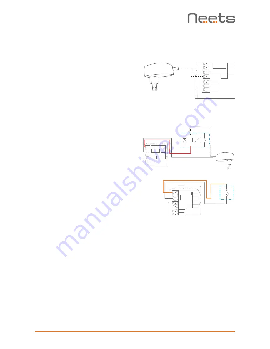
Power input port
Connect the OsCar to the supplied universal
mains AC power adaptor. Using the supplied 2
pole screw block terminal connect white/black
wire to 12V and black wire to GND.
I/O ports
The Neets Control – OsCar has 1 I/O onboard.
They can be used for external keyboard, PIR
(movement) sensor, keyboard lock, extra relay
and so on.
The port is not potential free, which means you
will need external relays, if you need to prevent
e.g. ground loops.
When used as output it is active low (when the
software says activated, the pin are tied to GND
through a FET transistor - also called open drain/
collector function). You can draw up to 24VDC/
500mA.
When used as input the voltage has to be below
1 Volt DC to be accepted as LOW, and above 4
VDC (but below 24 VDC) to be accepted as high.
GND
I/O 2
I/O 1
GND
+12V
RX
LAN
TX/IR
GND
GND
I/O 2
I/O 1
GND
+12V
RX
LAN
TX/IR
Relay control
Input trigger
Relay
Switch
Neets Control
OsCar, DK
P/N#: 310-0255
GND
GND
I/O 2
I/O 1
GND
+12V
RX
LAN
TX/IR


