Nedap PowerRouter Installation Manual Download Page 13

EN

13

7 Malfunctions and errors

This chapter provides information in case of a malfunction or error of the PowerRouter.

The PowerRouter will indicate the malfunction on the unit both by the LED indicators and on the display. The malfunction may be of any 
kind, either inside the unit or somewhere in the PV system. The unit will not operate until the fault has been corrected. The different error 
codes and possible causes are addressed in this section. Refer to myPowerRouter.com for the latest error list.
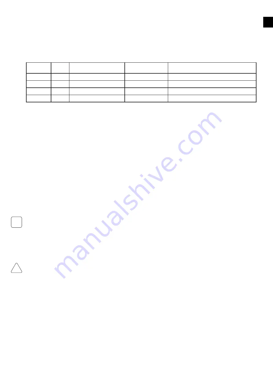
LED indication

In case of malfunction the LEDs will either be OFF or FLAShING as follows:

Operation

LED 
color

LED: 

ON

LED: 

OFF

LED: 

FLASHING

Operational

blue

when unit is operational

when unit is off or error

n.a.

Charging

blue

when batteries are charged

when unit is off or error

when capacity of the batteries are lower then 30% 

Grid

blue

when grid is connected

when no grid or off 

Grid available not connected

Error

red

when error (*)

n.a.

when one module / function down (**)

*  Requires service intervention
** Error may resolve itself; other module/functions active.

How to deal with errors

An error may prevent the system from operating. Before the system can operate again, the error has to be cleared. Errors are cleared 
automatically by the system if the error condition disappears. When the error message stays, press a button (YES or NO or UP/DOWN) on 
the PowerRouter to clear the error. Also the error message can be cleared using the installation software tool or via the internet.

Clear error message procedure:
1.  Press NO for at least 3 seconds

Troubleshooting

If you encounter difficulty with the operation of your PowerRouter, please follow these steps in an effort to correct the problem:
• 

Check the LED display

• 

Check and record the error message on the LCD display or other communication system available and take appropriate action to 
correct the issue by referring to the error codes in Appendix B

• 

If the system problem persists, contact your installer/dealer

When contacting your installer, provide the following information:
• 

Serial number

• 

Model number

• 

Short description of the problem

• 

Display message

• 

Error codes listed in the Service/Error history menu

Error codes are listed in Appendix B and will also be available on myPowerRouter.com.

8 Cleaning and maintenance

This chapter describes the cleaning and maintenance of the PowerRouter.

Clean every 12 months (once per year) the housing with a dry cloth and check that there is no airflow obstruction. Remove any dust build-up 
from the locations as indicated. Check the PowerRouter and the cables for visible external damage on a regular basis.

When cleaning the airflow holes inside the housing, cut off the power from the PowerRouter unit by decommissioning or by using a bypass 
switch.
Internal cleaning is only to be carried out by certified persons. Contact your installer/dealer if you find any defects. Do not perform any repair 
work yourself.

i

!

CAUTION

Summary of Contents for PowerRouter

Page 1: ...the PowerRouter PowerRouter Solar Battery Installation Manual...

Page 2: ...tandby 1 2 3 4 x 4 x 2 x 2 x 4 5 6 Standby Standby Standby Standby Standby Standby Standby Standby min 300 mm min 800 mm Max 40 C Min 10 C i 20 KG A A A A A B B Drill template for the PowerRouter Dril...

Page 3: ...C LOCAL OUT AC GRID USB ETHERNET RJ45 CAN BUS CAN NO NO NC NC AC GRID AC LOCAL OUT 2 1 internet router PC laptop Mac to the router Cat5 network cable of a suitable length the PowerRouter to the router...

Page 4: ...Settings menu Service menu Status menu System Reset Selftest Errors Install Wizard Display Date Time Language Battery Solar Grid Battery Solar Grid Internet connections 13 14 YES NO ON OFF Operationa...

Page 5: ...te 20 Manuel d installation Page 34 Installatie handleiding Bladzijde 48 Manuale d installazione Pagina 62 Manual de instalaci n P gina 76 Manual de instala o P gina 90 N V Nederlandsche Apparatenfabr...

Page 6: ...formation that you should know and use to ensure optimal operation of the system A bullet with a number refers to an illustration with the same number For illustrations refer to pages 2 4 Contents To...

Page 7: ...e into account the following guidelines cautions and warnings when choosing a mounting location for the PowerRouter The PowerRouter is designed for indoor installations IP21 Do not install the PowerRo...

Page 8: ...n in a safe and efficient manner follow the steps in the right order Before wiring the PowerRouter make sure that all wires connected to the PowerRouter are not live by turning off all disconnects and...

Page 9: ...PowerRouter Read the label on the battery Battery charging stations must be located in designated battery charging areas This is because of the dangers of hydrogen gas and battery acid Do not smoke or...

Page 10: ...e with the install wizard and installation software tool see also clause 6 2 The left contacts can be used for grid alarms the right contacts can be used for battery alarms 5 Commissioning This chapte...

Page 11: ...or the end user depending on the configuration The restart duration is less than 1 minute Reset procedure 1 Enter the service menu 2 Select Reset 3 Press YES to continue 4 Press YES to start the Reset...

Page 12: ...ill not be used if fixed float charge characteristic is set 28 8 V when 3 stage is set 28 0 V 30 0 V Low battery alarm ON Low battery alarm relay will be activated if battery voltage falls below set v...

Page 13: ...outer to clear the error Also the error message can be cleared using the installation software tool or via the internet Clear error message procedure 1 Press NO for at least 3 seconds Troubleshooting...

Page 14: ...d in Appendix D Solar 8 Disconnect AC wiring Grid Load The PowerRouter can now be removed for disposal or repair Decommissioning should only be carried out by certified persons Contact your installer...

Page 15: ...or inappropriate operation insufficient ventilation of the unit failure to observe the applicable safety regulations force majeure e g lightning overvoltage storm fire cosmetic shortcomings which do...

Page 16: ...isconnects loads B004 S Battery temperature too high measured by the external temperature sensor Check ambient temperature of battery storage room Provide sufficient cooling B005 S Battery temperature...

Page 17: ...upply voltages out of range D029 S Cold start failed D011 S Load voltage too low Check grid voltage D012 S Load voltage too high D013 H Load short circuit Check load D023 H Current overload Disconnect...

Page 18: ...anti islanding regulations electronic fused 6W interactive display with 4 button operation ethernet RJ45 TCP IP 1 second PR50SB BU PR37SB BU PR30SB BU 5 5 kWp and 15 A per string 4 kWp and 15 A per st...

Page 19: ...n the connector locking mechanism PV disconnection procedure 1 Insert PV MS tool with the pins to the connector 2 Pull the PV connector out of the PowerRouter This tool is not delivered with the Power...

Page 20: ...nformationen zu finden die f r einen optimalen Betrieb der Anlage anzuwenden sind Ein nummeriertes Aufz hlungszeichen weist auf eine Abbildung mit derselben Nummer hin Die Abbildungen befinden sich au...

Reviews: