


5.
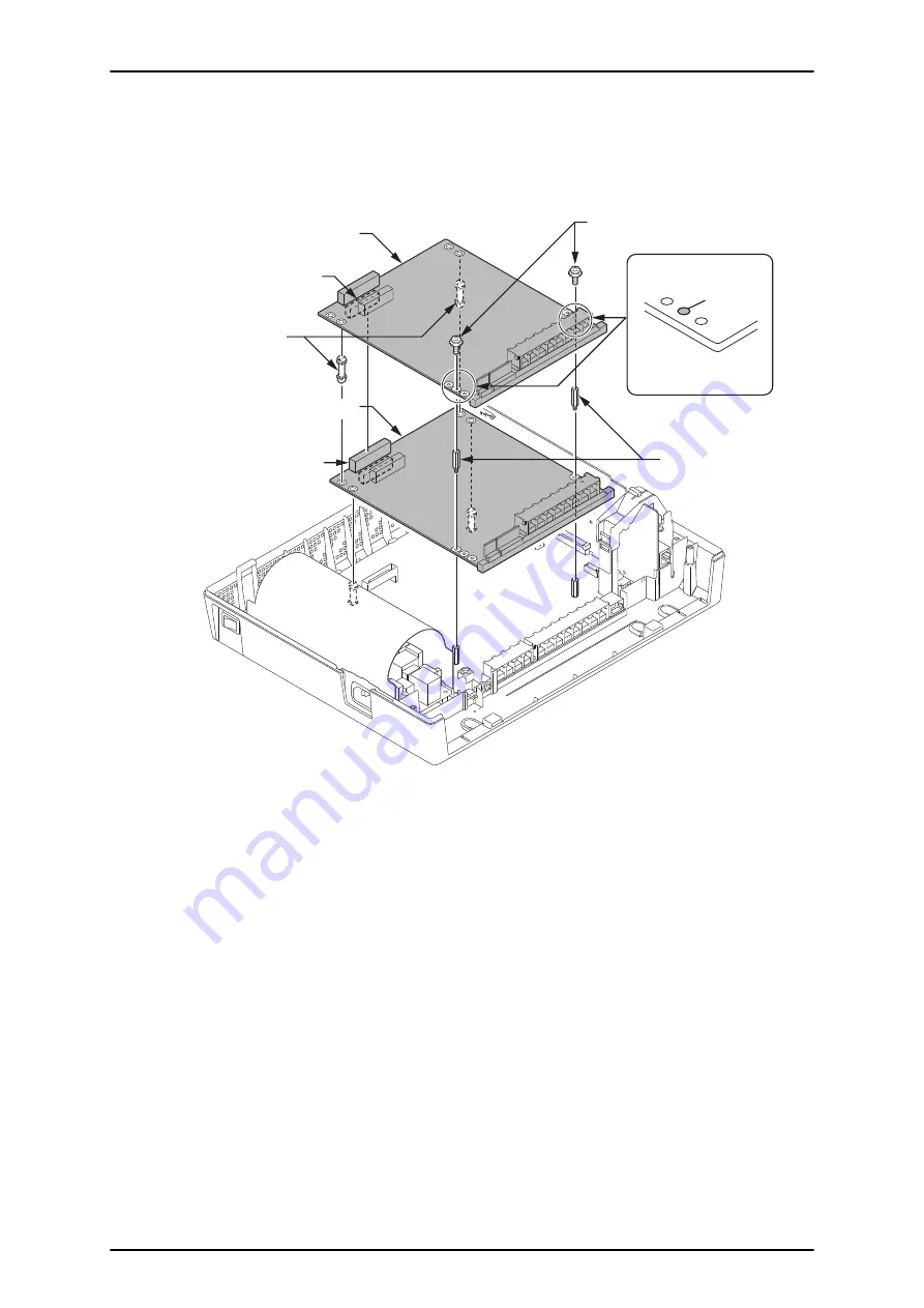
In case a 2nd PCB is mounted, insert two Nylon-spacers into the specified holes, and fasten two
Metal-spacers into the specified holes. (Both Nylon and Metal spacers are provided with 408E/
008E/000E/1PRIU)
If no more Expansion interface card is mounted on the 2nd PCB, fasten two screws to secure the
2nd PCB to the top of the 408E/008E/000E/1PRIU.
Expansion Interface Card
(2nd PCB)
J1
J2
Nylon-Spacers
Metal-Spacers
Screws
Expansion Interface Card
(1st PCB)
Screw position
Both sides are
the same.
2nd EXP.
PCB
Figure 2-66 Mounting the 2nd Expansion Interface Card
ISSUE 3.0
SL1000
Hardware Manual
2-45
Summary of Contents for SL1000
Page 1: ...Hardware Manual A50 031170 001 GE ISSUE 3 0 November 2012...
Page 12: ...MEMO SL1000 ISSUE 3 0 x Hardware Manual...
Page 16: ...MEMO SL1000 ISSUE 3 0 R 4 Regulatory...
Page 126: ...MEMO SL1000 ISSUE 3 0 3 8 System Start Up...
Page 140: ...MEMO SL1000 ISSUE 3 0 4 14 Maintenance...


