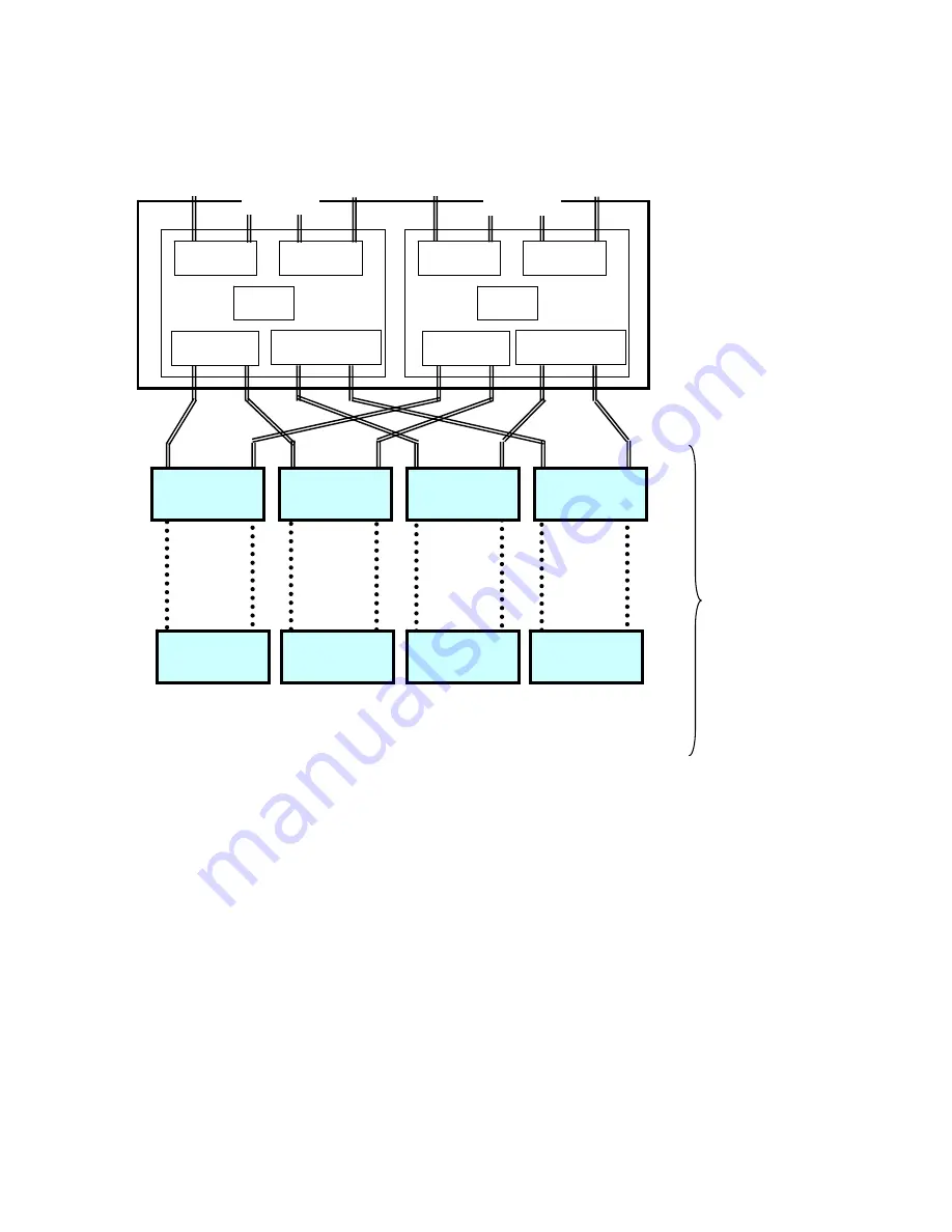
NEC S2900 User Manual Download Page 62


45


Host Port 

Host Port 

Base Disk Port 

Host Port

Host Port

Cache

Cache 

Port#0 

Port

 #1 

Port

 #2 

Port

 #3 

Up to 4DES 
four each PORT 

Extended Disk Port 

Base Disk Port

Extended Disk Port

DP#

Extended DE 

(FC or SATA)

Extended DE 

(FC or SATA)

Extended DE 

(FC or SATA)

Extended DE 

(FC)

Extended DE 

(FC or SATA)

Extended DE 

(FC or SATA)

Extended DE 

(FC or SATA)

DE:Disk Enclosure 

DP#1

DP#2

DP#3

CONT#0 

CONT#1

Extended DE 

(FC)

Summary of Contents for S2900

Page 1: ...ce and refer to the CAUTION and WARNING statements whenever necessary All rights reserved by NEC Corporation This document must be used solely for the purpose for which it was furnished by NEC Corpora...

Page 2: ...heir respective trademark owners Remarks 1 No part of this manual may be photocopied in any form without prior written consent from NEC 2 The information in this manual is subject to change without no...

Page 3: ...rgy and if not installed and used in accordance with the instruction manual may cause harmful interference to radio communications Operation of this equipment in a residential area is likely to cause...

Page 4: ...Indicates there is a risk of death or serious injury CAUTION Indicates there is a risk of burn or injury Risks and the necessary actions to reduce risks are indicated individually by the following sy...

Page 5: ...m battery Do not remove the lithium battery The lithium battery may explode when it is brought close to fire or when immersed in water Dispose of the controller according to local ordinances Contact y...

Page 6: ...adius of optical fiber shall be 30 mm Dust and or dirt may attenuate the optical power of optical fiber causing data errors to occur Clean any optical fiber cable whenever it is inserted into the mati...

Page 7: ...isk array unit that pose a possible danger and to inform the user that a hazardous situation may arise when operating the disk array unit Do not intentionally remove or damage any of the labels If you...

Page 8: ...v...

Page 9: ...vi...

Page 10: ...vii...

Page 11: ...it as well as the manual of the operating system in use NEC Storage BaseProduct software needs to be purchased separately before using the disk array unit Various options such as the FC disk drive opt...

Page 12: ...any repairs 2 Inspection After unpacking check that all the components listed in the table below are provided If any of the components is missed contact your sales representative Next inspect the disk...

Page 13: ...x NF2900 SR40E...

Page 14: ...User s Guide also uses the following symbol Symbol Description Supplement of the text This User s Guide uses the following terms to indicate specific devices Disk array unit NF2900 SR40E Array control...

Page 15: ...Connection Procedures 23 4 1 Installation and Connection Procedures 23 5 Connection of the Disk Array Unit 25 5 1 Notes on Connection of the Disk Array Unit 27 5 2 Connection of the Disk Array Unit 28...

Page 16: ...al Conditions 99 9 4 Power Specification 99 9 5 External Dimensions and Weight 99 9 6 Life Expectancies of Components 99 Appendix A Features of the Disk Array Unit 100 1 Battery Backup 100 2 Repair Ti...

Page 17: ...uct Setting 120 2 3 Activation on Modification of FC Port Configuration 121 Appendix D Installing Unit into a Rack 122 1 Installing the Rack mount Kit Accessory into an NEC Storage Rack 122 1 1 Instal...

Page 18: ...tallation and Handling of the Disk Array Unit 1 1 Note on Carrying Disk Array Unit Be sure to support the bottom of the disk array unit when carrying it Hold the front or side bottom of the disk array...

Page 19: ...ea of high humidity If so a fault or electrical shock may occur Do not install the disk array unit in an environment of chemical steam emission or an area where the disk array unit may come in contact...

Page 20: ...shock and or fire may occur The disk array unit can accept power between 100 240 VAC 50 60 Hz Using power of different voltage may cause electric shock smoke and or fire to occur Do not install the d...

Page 21: ...rsonal injury or failure of the unit Do not let any liquids such as water into the disk array unit If so you may be electrically shocked or the unit may become defective If liquids do enter into the d...

Page 22: ...olored In addition note that spraying insecticide on any surface may cause the surface to become deformed or discolored It is recommended to clean the inside of the disk array unit periodically This i...

Page 23: ...it is recommended to contact your maintenance engineer for inspection and or repair The array controller and the disk enclosure weigh 34 kg or more Hold the array controller and disk enclosure firmly...

Page 24: ...7...

Page 25: ...spare disk The use of this hot spare feature as well as the auto repair feature allows the data in the defected disk drive to be automatically recovered in the spare disk as soon as a disk drive becom...

Page 26: ...2 PDN12 PDN11 PDN11 PDN11 PDN10 PDN10 PDN10 PDN9 PDN9 PDN9 PDN8 PDN8 PDN8 PDN7 PDN7 PDN7 PDN6 PDN6 PDN6 PDN5 PDN5 PDN5 PDN4 PDN4 PDN4 PDN3 PDN3 PDN3 PDN2 LDN0 RAID5 PDN2 LDN0 RAID5 PDN2 LDN0 RAID5 Spa...

Page 27: ...g table shows the backup time when two battery backup units are installed and they are both fully charged The following conditions are imposed to make the write cache preservation feature effective Tw...

Page 28: ...unit in a real time mode NEC Storage Manager also enables you to set the following parameters through the host computer Setting of the RAID configuration RAID 1 5 6 10 50 and hot spare disk Resetting...

Page 29: ...ame rotational speed is required for configuring logical drives 1 Two modes 66 mode and 80 mode can be selected according to capacity efficiency The RAID levels have the following characteristics Leve...

Page 30: ...g the lock with the accessory key and pulling out toward you with your hands hooked on the both sides of the bezel In this state the accessory key cannot be pulled out To pull the key out from the fro...

Page 31: ...ackup units installed in the disk array unit 4 Battery Backup Units BBU0 BBU1 The battery backup units are installed to protect the data remaining in the cache memory at the occurrence of a power inte...

Page 32: ...ray controller See Section 3 4 Power Supply for the Array Controller for details 2 Controllers CONT0 CONT1 The array controller boards are provided to control the disk array unit See Section 3 5 Contr...

Page 33: ...e occurrence of a power interruption Turning off the battery backup unit disables write cache feature 2 Check terminal The check terminal is provided for maintenance inspection of the battery backup u...

Page 34: ...down by a single failure To ensure this functionality connect two power cords at the rear of the array controller 2 Power switch The power switch is used to turn On Off the power of the array controll...

Page 35: ...hts green when the AC power is supplied to the array controller and the power switch is set to ON The LED is off if the power switch is set to OFF or should a fault occur in the power supply 5 POWER F...

Page 36: ...uarantee the proper operation of the disk array unit replace the controller cooling fan immediately if a fan failure occurs 2 FAN LED FAN0 FAN1 orange The FAN LED lights orange if the cooling fan for...

Page 37: ...een in normal operation The LED will not blink if there is a problem or during the power on initialization sequence 7 FC connector for connection of a disk enclosure DP0 DP1 The FC connectors are used...

Page 38: ...connector The MODEM connector is used to connect a modem for fault notification 16 Slot for NF2900 Event Logging Tool Use this slot to insert the SD card which stores the events logged by the control...

Page 39: ...onnection 2 LINKUP LED DL2 DL3 A LINKUP LED lights green if the respective FC connector FC port becomes operable links up These LEDs flash during the self test or initialization sequence just after po...

Page 40: ...Check of components in package Check the components in the package following Check of Components in Package If any component is missing contact your sales representative Connection of Host Bus Adapte...

Page 41: ...parameters For setting parameters including RAID level and disk assignment use the NEC Storage Manager or contact your maintenance service representative Check the resource status for disk array unit...

Page 42: ...t angle Proper insertion allows the connector to be inserted to the mating connector smoothly without excessive force If the connector cannot be inserted smoothly do not insert it by force but check t...

Page 43: ...26...

Page 44: ...ect the array controller with a disk enclosure be sure to use the CONT DE cable provided with the disk enclosure or the NEC specified CONT DE cable NF9120 SJ34E 2 Cable length limit It is important to...

Page 45: ...t two host bus adapters with the host system Two LC LC cables or two SC SC cables and two FC conversion cables are necessary for connecting the host bus adapters a With the host bus adapter connectors...

Page 46: ...he FC disk enclosure SATA disk enclosure is optional See Section 6 1 Addition of a Disk Enclosure Connect the disk array unit with the host unit by using an FC cable in the following procedure FC conv...

Page 47: ...that the power switch on the disk array unit and those on the host system are set to OFF and the plugs of the power cords are removed from AC outlets a Power supply for array controller OFF ON b Power...

Page 48: ...apter or the FC AL switch connectors of the SC type Use the available optionally FC conversion cable NF9310 SJ10E The cable has different size connectors at the ends Push the smaller connector into th...

Page 49: ...he other FC disk enclosure SATA disk enclosure If you have attached the DE port NF2900 SP02E to the NF2900 SR40E use the FC cable HSSDC HSSDC provided with the DE port or available optionally CONT DE...

Page 50: ...ion order When the ENC ID switches of the left and right adapters are set differently the FAULT LEDs on the adapters flash and the disk enclosure is not started If different values are set for the ENC...

Page 51: ...34 Outline of cable connections and settings of the ENC ID switches Sample configuration 1 NF2900 SR40E 1 NF2500 SE42E 8...

Page 52: ...35 Sample configuration 1 NF2900 SR40E NF2900 SP02E NF2500 SE42E 16...

Page 53: ...rvice Engineer or NEC trained maintenance service representative who has expert knowledge of the disk array unit To make any of the sample connections you need to connect two host bus adapters install...

Page 54: ...ng a FC cable in the following procedure 1 Check of the power supply Make sure that the power switch of the disk array unit and that of the host unit are set to OFF and that the plugs of the power cor...

Page 55: ...so connect the other host bus adapter in the host system to the FC AL switch via the FC cable b If the host bus adapter connectors and FC AL switch connectors are of the SC type Use the available opti...

Page 56: ...disk enclosures in Section 5 2 for the procedure 4 Settings of switches Connect the maintenance PC and set an AL PA for each controller Also set an enclosure ID by using the ENC ID switch on each dis...

Page 57: ...C Storage Manager management software is installed to Ethernet Notes regarding LAN cables for use with NEC Storage Manager and the maintenance PC Use a straight through Shielded Twisted Pair STP cable...

Page 58: ...u may be electrically shocked The disk array unit has a redundant power configuration to prevent the entire unit from shutting down due to a single failure Therefore connect two power cords to both th...

Page 59: ...screw as shown in the figure below Insert the power cord and then secure the power cord by firmly fitting the power cord stopper into the receptacle of the power cord When connecting the power supply...

Page 60: ...3 Connection of power plug Insert the plug of the power cord to an AC outlet Because the plug has a grounding pin use an AC outlet with grounding terminals for the connection as shown in the figure be...

Page 61: ...f a DE port NF2900 SP02E up to 16 disk enclosures and up to 240 disk drives may be installed Product name FC disk enclosure NEC Part number NF2500 SE42E SATA disk enclosure NEC Part number NF2500 SE82...

Page 62: ...Up to 4DES four each PORT Extended Disk Port Base Disk Port Extended Disk Port DP Extended DE FC or SATA Extended DE FC or SATA Extended DE FC or SATA Extended DE FC Extended DE FC or SATA Extended D...

Page 63: ...rray unit to the FC IN connector on Adapter 1 ADP1 of the FC disk enclosure NOTES Extension of the disk port is required for the connections with DP 2 3 by extension of the option Connection of a SATA...

Page 64: ...ust be set a Setting of the ENC ID switch on FC SATA disk enclosure Set an ENC ID by using the ENC ID switch on each adapter of the FC SATA disk enclosure The ENC ID switches on both adapters are fact...

Page 65: ...48 capacity and rotational speed be used together...

Page 66: ...ceived with the disk enclosure into the power plug of the power supply of the disk enclosure Extend the clamp section of the AC cable clamp fit it to the AC cord and lock the clamp section lightly The...

Page 67: ...unit will not recognize the disk enclosure just because cabling has been connected between the units Provide the proper settings for the disk enclosure through the maintenance PC Or contact your serv...

Page 68: ...t the inside of the Disk Array unit has sharp edges electrical connections and other potential dangers to your hands and fingers Do not disassemble or modify the additional DE port Doing so may cause...

Page 69: ...a new DE port in this state the data remaining in the cache memory will be lost Perform the procedure explained in Section 7 2 2 Notes on turning off the AC power so as not to leave any unwritten data...

Page 70: ...ached to the upper part of the DPE stack connector Be sure to keep removed blank panel in a safe place After removing a DE port from the unit be sure to install a blank panel into the slot If using th...

Page 71: ...il fitting in the connector firmly After confirming that the connector is fit in firmly secure the DE port with three screws two screws you removed in 5 Removal of blank panel and one screw provided w...

Page 72: ...he cables removed from the controller in Step 3 Removal of cables to the mating connectors as before Close the ejector after connecting the cables Firmly push the ejector the part indicated by the arr...

Page 73: ...e disk array unit a label indicating the options available for installation is placed to allow any installed options to be known by an external view If the DE port is added write a round mark at the c...

Page 74: ...d with two 1GB cache memory cards on each controller To use a larger quantity of cache memory for improving the performance features of the disk array unit up to four cache memory cards can be added f...

Page 75: ...ve If you add a new DE port in this state the data remaining in the cache memory will be lost Perform the procedure explained in Section 7 2 2 Notes on turning off the AC power so as not to leave any...

Page 76: ...59 Be careful as this may be hot...

Page 77: ...of the socket Confirm that they are seated properly Until the cache memory is secured by the levers push the cache memory along the connector rail as far as it will go Be careful not to apply excess...

Page 78: ...Connect the cables removed from the controller in Step 3 Removal of Cables to the mating connectors as before Close the ejector after connecting the cables Firmly push the ejector the part indicated...

Page 79: ...Updating the Option label On the disk array unit a label indicating the options available for installation is placed to allow any installed options to be known by an external view If additional cache...

Page 80: ...63 Note The figure above indicates the addition of NF2900 SC01E...

Page 81: ...cess operation is indicated at the host system do not apply vibrations and or shock to the disk array unit Because the disk array unit is a precision device it should not be subject to any hard vibrat...

Page 82: ...rn on the two power switches at the rear of the disk array unit Alternatively turn on the disk array unit and all the additional FC or SATA disk enclosures connected with the disk array unit at the sa...

Page 83: ...66 3 Host system 2 Power switches of array controller May be turned on at the same time the power switches of disk enclosures are turned on...

Page 84: ...the data remaining in cache memory in the disk array unit onto the disk drive according to the following procedure Then turn off the AC power according to the procedure explained in 3 Turning off the...

Page 85: ...m is shut down it writes the remaining cache data into the disk array unit Before turning OFF the power of the disk array unit confirm that no cache data remains on the host system and no data remains...

Page 86: ...osures Alternatively turn off the array controller and all the FC disk enclosures connected with the array controller at the same time The disk array unit has a redundant power configuration to preven...

Page 87: ...only be set in RAID levels 1 5 6 10 or 50 Set the spare disk by using the NEC Storage Manager or contact your Service Engineer or NEC trained maintenance service representative who has expert knowled...

Page 88: ...g fans is found turn off the power and disconnect the power plugs from the AC outlets Then ask your maintenance engineer to inspect and repair the disk array unit immediately Using the disk array unit...

Page 89: ...s adapter connected with the FC cable does not light Cause Countermeasures The FC cable is not connected correctly Insert the connector of the FC cable until a click is heard See Chapter 5 Connection...

Page 90: ...area in which it easily suffers vibration and or shocks Install the disk array unit referring to Chapter 1 Notes on Installation and Handling of Disk Array Unit The power is turned off or the reset bu...

Page 91: ...orange The array controller power supply with the POWER FAIL LED being on is defective The BBU FAIL LED on an array controller power supply lights orange The battery backup unit corresponding to the...

Page 92: ...ace all the cache memories and DE ports as well as the controller or contact your maintenance service representative to identify the defective unit for replacement Replacement procedure 1 Identify the...

Page 93: ...that of the defective controller 4 Open the ejectors of the controller for replacement insert the controller into the slot until firmly seated The lock of the protection shutter that closed when the...

Page 94: ...t the startup immediately after replacement write back the IP address of the old controller to the new controller If the controller was replaced with a new one the system starts using the IP address s...

Page 95: ...cooling fan is FAN0 or FAN1 depending on the FAN LED being on 2 Loosen the two set screws at the upper right and lower left corners of the defective controller cooling fan to pull it out from the slot...

Page 96: ...ctive power supply may be replaced with the other power supply remaining ON Replacement procedure 1 Identify the defective power supply by the POWER FAIL LED of the power supply 2 Set the switch of th...

Page 97: ...5 Make sure that the switch of the power supply for replacement is set to OFF and the power cord is removed from the power plug 6 Slide the removal protection mechanism inward as shown in the figure b...

Page 98: ...e array controller push it as far as it will go and then secure it with the screw Incorrect insertion may cause a malfunction 8 Insert the power cord into the power plug of the replaced power supply a...

Page 99: ...ontroller 2 Loosen the three screws securing the battery cover of the array controller to remove the cover 3 Set the battery switch of the defected battery backup unit to OFF 4 Loosen the two set scre...

Page 100: ...he notch on the chassis slide the unit to the left and insert it slowly When inserting the battery backup unit into the array controller push it as far as it will go and then secure it with the screws...

Page 101: ...e data to be lost due to interruption of redundancy Except in a RAID6 environment where 3 disk drives wold need to fail If the FAULT LED on a disk drive lights replace the disk drive immediately Perfo...

Page 102: ...t is provided with the replacement disk drive and then put the label on the replacement disk drive Location label 4 With the ejector of the new disk drive opened engage the guides on the top and botto...

Page 103: ...If the Auto Repair feature is set to OFF issue a recovery instruction from the management software in manual mode to start data recovery Otherwise the reduced state reduce shown as the logical disk s...

Page 104: ...acing a power supply for the disk enclosure prepare the new power supply before removing the old one and then replace it within about 3 minutes The following units of the FC disk enclosure generate he...

Page 105: ...power cord Then pull out the receptacle of the power cord from the power plug of the power supply for the disk enclosure 3 Loosen the screw securing the ejector put your finger on the protrusion shown...

Page 106: ...ective power supply When the defective power supply comes out guide it with both hands and slowly remove it 4 Confirm that the power switch of the new power supply for the disk enclosure is OFF and th...

Page 107: ...pulled toward you hold the new power supply for the disk enclosure with both hands and insert it into the slot 6 Push the protrusion shown in the figure of the ejector to turn the ejector and push in...

Page 108: ...e screws Incorrect insertion may cause a nother power supply failure 8 Insert the receptacle of the power cord shipped with the FC SATA disk enclosure into the power plug of the power supply for the d...

Page 109: ...f the array controller and disk enclosure remain ON Replacement procedure 1 Identify the defective adapter with the FAULT LED on the adapter being lit Remove all the cables connected to the defective...

Page 110: ...adapter for replacement is set to the same value as that of the defective adapter If the adapter is installed with a different ENC ID setting a link failure may occur in the worst case 5 Insert the re...

Page 111: ...er is seated properly and secure the ejector with the screw When inserting the adapter into the disk enclosure push it as far as it will go and then secure it with the screws Incorrect insertion may c...

Page 112: ...mber of the disk array unit are shown at the locations in the figure below Manufacturing number label of array controller Manufacturing number label of power supply for array controller Manufacturing...

Page 113: ...perating environment Therefore the components should be replaced periodically For their replacement contact your maintenance service representative Service life of the disk array unit 5 years 1 Repair...

Page 114: ...ray Unit The table below shows the basic specifications of the disk array unit Hot spare feature Provided Host interface specification FC AL Optical Data transfer rate of host interface 400 MB S or 20...

Page 115: ...disk drive 300GB 10 000rpm NF2500 SM423E Additional FC disk drive 1 73GB 15 000rpm NF2500 SM424E Additional FC disk drive 1 147GB 15 000rpm NF2500 SM802E Additional SATA disk drive 1 400GB 7200rpm NF2...

Page 116: ...9 4 Power Specifications The table below shows the power specifications of the disk array unit Array controller Disk enclosure Input voltage 100 to 240 VAC 10 50 60 Hz Maximum power consumption 330 VA...

Page 117: ...r off once and then on again 2 Repair Time The repair time is set to 12 hours by default The repair time can be set in the range from 0 fastest to 24 hours Depending on the disk capacity the repairs m...

Page 118: ...ay provide the installation service at an additionall charg for releasing the license lock and making settings Contact your maintenance service representative if necessary 4 1 Port Mode Accessible log...

Page 119: ...destination disk To use this feature the specific software Remote DataReplication NEC Storage S2900 sold separately is required Refer to the User s Guide provided with the software Before the Dynamic...

Page 120: ...first step No status change Res SYNCING Restore SYNCED Change to fault state and abort of copy operation Any pair in which a fault has occurred is recovered by the following operation 1 Issues Forced...

Page 121: ...will not function properly Other NEC software products are available for the disk array unit ask your sales representative For more information 12 Updating of Control Software When you update the con...

Page 122: ...e license lock and changing settings Contact your maintenance service representative if necessary 13 1 Note on Using Snap Shot SnapShot manages the difference data between the logical disk as the copy...

Page 123: ...on of a RAID level Select the RAID level carefully because it has certain influences on system performance and capacity See Section 2 4 RAID Configuration for details The LD bind requires the specific...

Page 124: ...rface and Internet Explorer Version5 0 or higher 2 Connect the PC to NF2900 in the one to one mode Connection via a hub may be possible However because the IP and MAC addresses are fixed a connection...

Page 125: ...er All the features on the left side of the screen will become available Notes 1 Because the IP and MAC addresses of the MNT s Ether port are set as described above do not connect the port to any LAN...

Page 126: ...ion Select 4 Configuration 1 Control Configuration Then set the following items Date Current year month and date Format YY MM DD Time Current time Format HH MM SS Unit Name Unit name After changing th...

Page 127: ...rt Configuration Select 4 Configuration 4 Port Configuration Then set the following items Port Port position Host type Host type to be selected from the pull down list Click the SET button to determin...

Page 128: ...111 1 2 3 FC Port Configuration Select 4 Configuration 5 FC Port Configuration to set the following items When WWN is not defined When WWN is defined...

Page 129: ...hexadecimal number The following two modes can be set currently Set either one Host Director Port 0000 Replication Director Port 0040 Switch Provide a setting for your Switch See Table 1 2 2 for the a...

Page 130: ...C 4B 4A 49 47 46 45 43 3C 3A 39 36 42 43 44 45 46 47 48 49 4A 4B 4C 4D 4E 4F 50 51 52 53 54 55 56 57 58 59 5A 5B 5C 5D 5E 5F 60 61 62 35 34 33 32 31 2E 2D 2C 2B 2A 29 27 26 25 23 1F 1E 1D 1B 18 17 10...

Page 131: ...ows2000 Solaris Linux AIX Basic value 10h Set to 1 if loop duplication occurs Miscellaneous Conforms to the additional rule in the server if any The basic value is 10h if no additional rule is defined...

Page 132: ...creen can be used to set the resource type On the DE columns set the locations of all installed DEs disk enclosures The information on the DEs with their check buttons checked is only set Select the P...

Page 133: ...116 DE Location View DE00 DE01 DE05 DE09 DE0 DE0 DE04 DE08 DE03 DE07 DE0 DE0 DE02 DE06 DE0 DE0...

Page 134: ...117 1 2 5 Network Property Select 4 Configuration 7 Network Property to set the following items...

Page 135: ...ke accessible from iSM without manager registration SNMP Valid Makes SNMP effective ON if checked Community Name Read permission for SNMP and community name of trap default value public 0 0 0 0 0 Regi...

Page 136: ...the Maintenance PC according to Section 1 2 2 1 Confirmation of FC Port Configuration Select 1 Status 2 Control Port Status to confirm the settings of FC Port Configuration When WWN is not defined Wh...

Page 137: ...Extended format xxxxb 0010b yyyyb 0000b zzh 00h 2 2 Confirmation of Base Product Setting Select 2 Condition 1 Condition View to confirm the resources being set The resource states are distinguished by...

Page 138: ...m to offline Next check the port s to be selected newly to set them online Set the on off status of the host ports on the CONT card Port On Off Switch Feature of Port On Off with host Only mounting po...

Page 139: ...NOTE The following procedures supposes that a rail is installed on the left part of a rack when the rack is viewed from its front Install a rail on the right part of the rack in the similar procedure...

Page 140: ...the rack Insert the provided screw into the hole at the bottom to secure the rail If the two small head screws are provided use them as shown in the right figure below Set screw Set screw Insert 1U pa...

Page 141: ...projections into the angle holes 5 With the inner held push the two set screws with a part for cable clamp into the female screws of the rail support and drive the screws equally Take note on the dire...

Page 142: ...ection on the rails and push it into the rack NOTE The unit is very heavy Be careful not to drop it while lifting Fasten four set screws at two left and two right points on the front of the unit The f...

Page 143: ...the following procedures supposes that a rail is installed on the left part of a rack when the rack is viewed from its front Install a rail on the right part of the rack in the similar procedure The...

Page 144: ...th angle holes use the rail as the rail support remains attached 8 Loosen the four flush screws at the rear end of the rail After loosing the screws make sure that the moving part of the rail can slid...

Page 145: ...below with the flush screw removed in step 2 loosely Make sure that the moving part of the rail can slide smoothly 11 Insert the top and bottom projections into the angle holes on the front of the ra...

Page 146: ...the rack with the screw holes of the rail and fix the rail with the attached set screws Use the set screw see the figure below 13 Pull the inner toward you and push the top and bottom projections int...

Page 147: ...s with a part for cable clamp into the female screws of the rail support and drive the screws equally Take note on the direction of the part for cable clamp Drive the four flush screws loosened in ste...

Page 148: ...n the right side of the rack install the other rail in the same procedure 16 Install the rack nut at the position shown in the figure below or the first hole on the projection at the top of the rail R...

Page 149: ...he rack NOTE The unit is very heavy Be careful not to drop it while lifting 18 Fasten four set screws at two left and two right points on the front of the unit The figure below only shows the right pa...

Page 150: ...port from the rail 19 Remove the rail support installed previously from each rail by removing four screws two on the front and the other two on the rear 20 Loosen four flush screws at the rear side of...

Page 151: ...sh screw 1 enclosed by a circle in the figure below 22 Install the attached bracket see the figure below with the flush screw removed in step 3 loosely Make sure that the moving part of the rail can s...

Page 152: ...with the label and fix the rail to the rack with the attached set screws Use screws see the figure below 24 Pull the inner toward you and with it held insert the two set screws with a part for cable...

Page 153: ...136 Drive the four flush screws loosened in step 1 and removed in step 3 securely 25 On the right side of the rack install the other rail in the same procedure...

Page 154: ...the figure below or the hole just above the set screw the first hole of the top of the rail 27 Lift the unit put the rear section on the rails and push it into the rack NOTE The unit is very heavy Be...

Page 155: ...28 Fasten four set screws at two left and two right points on the front of the unit to fix the unit The figure below only shows the right part of the unit Fix the left part of the unit similarly Scre...

Page 156: ...nt kit is to be separately purchased Ask your sales representative for details 2 1 Installation of Rails The procedure explained in this section covers the rail installed to the left side of the rack...

Page 157: ...e unit and engage the hook with the cutout NOTE Two cutouts are provided one is for new rack and the other is for old rack The outer cutout should be used for the new rack while the inner cutout is us...

Page 158: ...ile holding the rail tighten the set screw M4 screw 33 Move to the rear of the rack First while pulling the rail toward you screw the set screw M5 screw into the lower female threaded hole Set screw S...

Page 159: ...e fixture where the cable tie has been passed through to the rack by screwing the set screw M5 screw into the upper female threaded hole 35 Firmly tighten the four flush screws Set screw Fixture Cable...

Page 160: ...Move to the front of the rack and push one rack nut into the round hole which corresponds to the cutout on the rail from the side Then push another rack nut into the fifth round hole from the top as...

Page 161: ...Lift the unit and place the rear section on the rails and push the unit toward the innermost of the rack NOTE The unit is very heavy Be careful not to drop it while lifting 38 Screw four set screws M5...

Page 162: ...NF9100 SK02E rack mount kit is to be separately purchased Ask your sales representative for details 3 1 Installation of Rails 39 Temporarily tighten two set screws 10 32UNF at both ends of the front...

Page 163: ...each rail fitting the round hole in the rail onto the screws in step 1 and temporarily secure it 41 Move to the rear of the rack and firmly secure each rail with two set screws 10 32UNF Screw Round ho...

Page 164: ...on the rails and then push it in NOTE The unit is very heavy Be careful not to drop it while lifting 43 At the front of the unit firmly tighten the four set screws 2 at right and left each 10 32UNF t...

Page 165: ...Old type Rack NOTE The Express old type racks are N8540 28 42U rack N8540 29 36U rack N8540 38 16U rack N8540 09 44U rack N8540 09AC 44U rack N8540 10E 35U rack and N8540 10AC 35U rack The Express ol...

Page 166: ...149 4 1 Installing the Rack Mount Kit Install the rack mount kit into the rack as shown in the figure Detail A for fixing the installed unit...

Page 167: ...on the rails and then push it in NOTE The unit is very heavy Be careful not to drop it while lifting 45 At the front of the unit firmly tighten the four set screws 2 at right and left each 10 32UNF t...

Page 168: ...e clamp for cable handling if necessary However always clamp the AC cord on the unit side see the figure below For other cables put several cables together and pass each set through repeat ties as per...

Reviews: