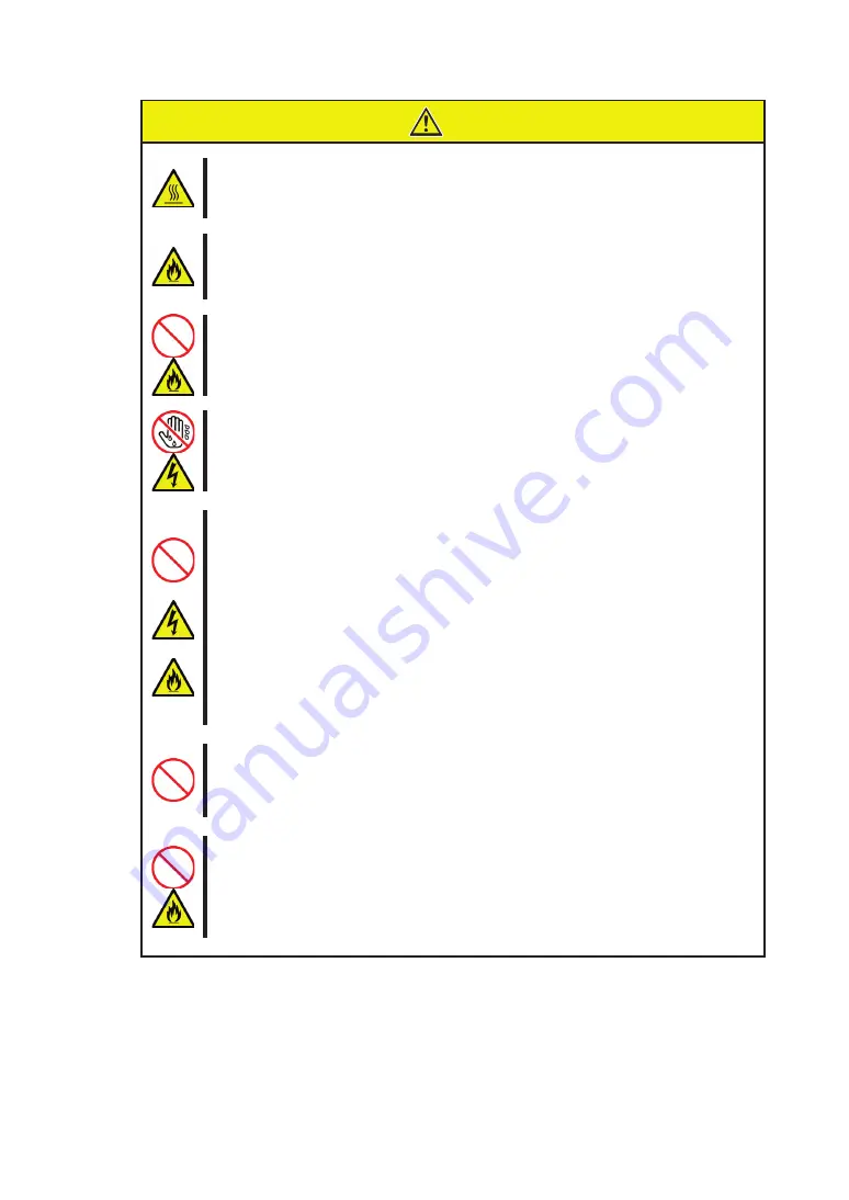
background image

㧗 䛻ὀព䛩䜛㻌

ᮏయ⿦⨨䛾㟁※䜢 㻻㻲㻲 䛻䛧䛯┤ᚋ䛿䚸⿦⨨ෆ䛾㒊ရ䛜㧗 䛻䛺䛳䛶䛔䜎䛩䚹༑ศ䛻෭䜑䛯䛣䛸䜢☜ㄆ
䛧䛶䛛䜙ྲྀ䜚௜䛡䠋ྲྀ䜚እ䛧䜢⾜䛳䛶䛟䛰䛥䛔䚹

☜ᐇ䛻᥋⥆䛩䜛㻌

ᮏ〇ရ䜢ᮏయ⿦⨨䛾 㻼㻯㻵 䝇䝻䝑䝖䛻᥋⥆䛩䜛䛸䛝䛿䚸☜ᐇ䛻ᕪ䛧㎸䜣䛷䛟䛰䛥䛔䚹᏶඲䛻ᕪ䛧㎸䜎䛺䛛
䛳䛯ሙྜ䚸Ⓨ↮䜔Ⓨⅆ䛾䛚䛭䜜䛜䛒䜚䜎䛩䚹

୰㏵༙➃䛻ᕪ䛧㎸䜎䛺䛔㻌

㟁※䝁䞊䝗䛚䜘䜃䜿䞊䝤䝹䛿᰿ᮏ䜎䛷䛧䛳䛛䜚䛸ᕪ䛧㎸䜣䛷䛟䛰䛥䛔䚹୰㏵༙➃䛻ᕪ䛧㎸䜐䛸᥋ゐ୙Ⰻ
䛾䛯䜑Ⓨ⇕䛧䚸ⅆ⅏䛾ཎᅉ䛸䛺䜛䛣䛸䛜䛒䜚䜎䛩䚹䜎䛯ᕪ䛧㎸䜏㒊䛻䜋䛣䜚䛜䛯䜎䜚䚸Ỉ⁲䛺䛹䛜௜䛟䛸
Ⓨ⇕䛧䚸ⅆ⅏䛾ཎᅉ䛸䛺䜛䛚䛭䜜䛜䛒䜚䜎䛩䚹

䛼䜜䛯ᡭ䛷㟁※䝁䞊䝗䜢ᣢ䛯䛺䛔㻌

ᮏ〇ရ䛾ྲྀ䜚௜䛡䚸ྲྀ䜚እ䛧䛾㝿䛿䚸䛼䜜䛯ᡭ䛷ᮏయ⿦⨨䛾㟁※䝁䞊䝗䛾ᢤ䛝ᕪ䛧䜢䛧䛺䛔䛷䛟䛰䛥
䛔䚹ឤ㟁䛩䜛䛚䛭䜜䛜䛒䜚䜎䛩䚹

ᣦᐃ௨እ䛾䜲䞁䝍䝣䜵䞊䝇䜿䞊䝤䝹䜢౑⏝䛧䛺䛔㻌

䜲䞁䝍䝣䜵䞊䝇䜿䞊䝤䝹䛿䚸ᣦᐃ䛩䜛䜒䛾䜢౑⏝䛧䚸᥋⥆䛩䜛⿦⨨䜔䝁䝛䜽䝍䜢☜ㄆ䛧䛯ୖ䛷᥋⥆䛧䛶䛟
䛰䛥䛔䚹ᣦᐃ௨እ䛾䜿䞊䝤䝹䜢౑⏝䛧䛯䜚䚸᥋⥆ඛ䜢ㄗ䛳䛯䜚䛩䜛䛸䚸䝅䝵䞊䝖䛻䜘䜚ឤ㟁䜔ⅆ⅏䜢㉳䛣
䛩䛣䛸䛜䛒䜚䜎䛩䚹㻌
䜲䞁䝍䝣䜵䞊䝇䜿䞊䝤䝹䛾ྲྀ䜚ᢅ䛔䜔᥋⥆䛻䛴䛔䛶ḟ䛾ὀព䜢䛚Ᏺ䜚䛟䛰䛥䛔䚹㻌

䞉◚ᦆ䛧䛯䜿䞊䝤䝹䜢౑⏝䛧䛺䛔䚹㻌
䞉䜿䞊䝤䝹䜢㋃䜎䛺䛔䚹㻌
䞉䜿䞊䝤䝹䛾ୖ䛻䜒䛾䜢㍕䛫䛺䛔䚹㻌
䞉䜿䞊䝤䝹䜢ᨵ㐀䞉ຍᕤ䞉ಟ᚟䛧䛺䛔䚹㻌

䜎䛯䚸㻲㼕㼎㼞㼑㻌 㻯㼔㼍㼚㼚㼑㼘 䜿䞊䝤䝹䜢ྲྀ䜚እ䛩䛸䛝䛿䚸䝷䝑䝏䜢ᢲ䛥䛘䛶䚸䝁䝛䜽䝍㒊ศ䜢ᣢ䛳䛶┿䛳┤䛠䛻ᘬ
䛝ᢤ䛔䛶䛟䛰䛥䛔䚹㻌
㻲㼕㼎㼞㼑㻌㻯㼔㼍㼚㼚㼑㼘 䜿䞊䝤䝹䛿䚸ᙜ♫ᣦᐃ䛾䜒䛾䜢౑⏝䛧䚸᥋⥆ඛ䜢䜘䛟☜ㄆ䛧䛯ୖ䛷᥋⥆䛧䛶䛟䛰䛥䛔䚹

㻲㼕㼎㼞㼑㻌㻯㼔㼍㼚㼚㼑㼘 䝁䝛䜽䝍䛻䜹䝞䞊䛫䛪౑⏝䛧䛺䛔㻌
ᖖ䛻 㻲㼕㼎㼞㼑㻌 㻯㼔㼍㼚㼚㼑㼘 䝁䝛䜽䝍䛿௜ᒓ䛾㜵ሻ䜹䝞䞊䜒䛧䛟䛿 㻲㼕㼎㼞㼑㻌 㻯㼔㼍㼚㼚㼑㼘 䜿䞊䝤䝹䜢᥋⥆䛧䛯
≧ែ䛷౑⏝䛧䛶䛟䛰䛥䛔䚹␗ᖖᨾ㞀䛜Ⓨ⏕䛧䛯ሙྜ䛻䝺䞊䝄ග䛷┠䜔⓶⭵䜢യ䜑䜛䛣䛸䛜䛒
䜚䜎䛩䚹㻌

⭉㣗ᛶ䜺䝇䛾Ꮡᅾ䛩䜛⎔ቃ䛷౑⏝䜎䛯䛿ಖ⟶䛧䛺䛔㻌

⭉㣗ᛶ䜺䝇䠄஧㓟໬◲㯤䚸◲໬Ỉ⣲䚸஧㓟໬❅⣲䚸ሷ⣲䚸䜰䞁䝰䝙䜰䚸䜸䝌䞁䛺䛹䠅䛾Ꮡᅾ䛩䜛⎔ቃ䛻
タ⨨䛧䚸౑⏝䛧䛺䛔䛷䛟䛰䛥䛔䚹䜎䛯䚸䜋䛣䜚䜔✵Ẽ୰䛻⭉㣗䜢ಁ㐍䛩䜛ᡂศ䠄ሷ໬䝘䝖䝸䜴䝮䜔◲㯤䛺
䛹䠅䜔ᑟ㟁ᛶ䛾㔠ᒓ䛺䛹䛜ྵ䜎䜜䛶䛔䜛⎔ቃ䜈䜒タ⨨䛧䛺䛔䛷䛟䛰䛥䛔䚹⿦⨨ෆ㒊䛾䝥䝸䞁䝖ᯈ䛜⭉㣗
䛧䚸ᨾ㞀䛚䜘䜃Ⓨ↮䞉Ⓨⅆ䛾ཎᅉ䛸䛺䜛䛚䛭䜜䛜䛒䜚䜎䛩䚹䜒䛧䛤౑⏝䛾⎔ቃ䛷ୖグ䛾␲䛔䛜䛒䜛ሙྜ
䛿䚸㈍኎ᗑ䜎䛯䛿ಖᏲ䝃䞊䝡䝇఍♫䛻䛤┦ㄯ䛟䛰䛥䛔䚹

ὀព

Summary of Contents for N8190-157A

Page 1: ...efore handling this product Please refer to this document if there is something that you do not understand or a problem occurs while using this product Store this guide close to this product for easy...

Page 2: ...ers and should be treated as such Note 1 No part of this document may be reproduced without consent 2 The content of this document may be changed without prior notice 3 No part of this document may be...

Page 3: ......

Page 4: ......

Page 5: ......

Page 6: ......

Page 7: ...ution are the terms used here to express the level of danger These terms mean the following Indicates a hazard that can lead to death or serious injury Indicates a hazard that can lead to burning inju...

Page 8: ...c shock Indicates a hazard that can lead to fire Prohibited Action Indicates a general prohibition Indicates prohibition of disassembly or modification Do not touch with wet hand Otherwise an electric...

Page 9: ...se an electric shock or fire as well as malfunctions of this product Do not handle this product during an electrical storm When installing this product in the computer please read the user s guide of...

Page 10: ...the cable Do not place any object on the cable Do not alter modify or repair the cable When disconnecting a cable push the latch hold the connector and pull it out straight Use only the Fibre Channel...

Page 11: ......

Page 12: ...arrying out the work However there is no need to do this if the internal optional device is hot swappable This internal optional device consists of static sensitive electronic components To avoid fail...

Page 13: ...ry Canada Class A Emission Compliance Statement Avis de conformit la r glementation d Industrie Canada CAN ICES 3 A NMB 3 A CE Statement Warning This is a Class A product In a domestic environment thi...

Page 14: ...users with sufficient knowledge in the general handling of operating systems such as Windows a keyboard and mouse and general I O devices Symbols Used in This Guide The following three symbols are us...

Page 15: ......

Page 16: ...ed software must be deleted before this product is transferred or sold Transportation When transporting this product please refer to the packing list to remove this product from the basic processing u...

Page 17: ...1 3 9 12 12 13 13 13 13 13 13 13 17 17 21 23 25 26 27 29 30 38 42 44...

Page 18: ...ations 45 1 2 Features 45 2 Components 3 Names and Functions 4 Setup 4 1 Selection and Installation of Bracket 49 4 2 Install the Card 51 4 3 Connecting Fibre Channel Devices 53 4 4 Installing the Dri...

Page 19: ......

Page 20: ......

Page 21: ......

Page 22: ......

Page 23: ......

Page 24: ......

Page 25: ......

Page 26: ......

Page 27: ......

Page 28: ......

Page 29: ......

Page 30: ......

Page 31: ......

Page 32: ......

Page 33: ......

Page 34: ......

Page 35: ......

Page 36: ......

Page 37: ......

Page 38: ......

Page 39: ......

Page 40: ......

Page 41: ......

Page 42: ......

Page 43: ......

Page 44: ......

Page 45: ......

Page 46: ......

Page 47: ...l Controller 1ch is a Fibre Channel host bus adapter card This product has a Fibre Channel interface connector Do not connect this product to a computer or Fibre Channel device that is not recommended...

Page 48: ...ded with the product If you find any of them are missing or damaged please contact the retailer you bought the product from 3 Names and Functions 4 LED Yellow Green 1 PCI Express connector 2 Bracket 6...

Page 49: ...Off Off Boot Failure Dead Board Off On POST Failure Dead Board Off Slow Blink Boot Failure after POST Off Flashing POST Processing in Progress On Off Failure While Functioning On On Failure While Fun...

Page 50: ...et Page 49 Selection of bracket to use for this product Install the card Page 51 Install this product in the computer Connecting Fibre Channel Devices Page 53 Connect Fibre Channel Devices to this pro...

Page 51: ...racket with the attached low profile one The procedure is as follows Exchange of a bracket uses the minus screwdriver suitable for the size of a screw Remove the SFP module temporarily Remove the dust...

Page 52: ...1 Return the lever of the SFP module to the home position and then insert the SFP module until you hear it click After insert all SFP modules put dust covers to them Follow the same procedure when the...

Page 53: ...computer is powered off its internal components such as hard disks are very hot Leave the computer until its internal components fully cool down before installing removing any component Connect firml...

Page 54: ...e can lead to damage Replace the SFP module removed in item 3 Return its lever to the home position and then insert SFP module until you hear it click If the SFP module is not correctly inserted to th...

Page 55: ...perature conditions Immediately after the computer is powered off its internal components such as hard disks are very hot Leave the computer until its internal components fully cool down before instal...

Page 56: ...oduct is connected to Fibre Channel device by Fibre Channel cable that is not recommended by NEC Corporation the product may malfunction or fail Use Fibre Channel cables under conditions that conform...

Page 57: ...refer to the N8190 157A 158A Setup Card and the user s guide of the computer together Is the driver for the Fibre Channel Controller installed Is the product installed in the computer correctly Pleas...

Page 58: ...r assigned to the Fibre Channel device close the Computer Management and try to access again 2 Reboot Computer if possible and try to access again For All OS Is the Fibre Channel where this product is...

Page 59: ...lled The computer z Confirm that no built in disk is connected to the computer which will be started from the Fibre Channel device If a built in disk is connected the system may not start or you may e...

Page 60: ...slot which installed this product this message is not displayed Refer to the computer s User s Guide for how to enable the Option Rom of PCI slot This product s BIOS menu consumes a lot of memories T...

Page 61: ...mple is just for your reference Some of them may be different depending on the computer or its configurations 4 When the menu is displayed select the port connected to the Fibre Channel device Then yo...

Page 62: ...ou selected a wrong number in the above step press Esc key to return to the previous window and select the correct one If you have selected the correct figure confirm that the Fibre Channel device is...

Page 63: ...u have selected a device you see a window to enter a starting number for the device s LUNs like 9 Enter 00 indicating LUN0 for the LUN starting number Then a window to select an LUN for the device is...

Page 64: ...11 Select Boot this device via WWPN Then you see Boot device s settings window again Confirm that the top item on the list is Used 12 Press Esc key to return to the menu like...

Page 65: ...13 Select Enable Disable Boot from SAN Then you see the settings window like 14 Select Enable and confirm that Boot BIOS is Enabled is displayed...

Page 66: ...key to return to the adapter list and setting ports by the same steps from 4 16 Now you have made settings to start installing an operating system on your Fibre Channel device Press Esc key to exit th...

Page 67: ...ration submenu in the SETUP utility of the computer Refer to the computer s User s Guide for how to use the SETUP utility 4 Select this product LPe16000B from the list of devices which UEFI driver loa...

Page 68: ...uct confirm the WWPN which you selected Refer Appendix B Confirm WWPN addresses after setup to find this product s WWPN If you have selected the correct WWPN confirm that the Fibre Channel device is p...

Page 69: ...1 Select Delete Boot Device and press Enter to display the registered Boot Devices list If there is no problem in this list press Esc to return to main menu If there are any wrong Boot Devices select...

Page 70: ...Channel boot device Press Esc key to return to the adapter list and setting ports by the same steps from 5 Press Esc to return to the adapter list If select Back to UEFI Device Manager and RECONNECT D...

Page 71: ...while the following message is displayed Then you see this product s BIOS menu Without enable the Option Rom of PCI slot which installed this product this message is not displayed Refer to the compute...

Page 72: ...simultaneously to reboot the computer Then start the steps from the beginning The above message sample is just for your reference Some of them may be different depending on the computer or its config...

Page 73: ...splayed By changing the Node Name header 2000 to 1000 you will get WWPN address Example Node Name 2000 0090 FA21 1128 WWPN address 1000 0090 FA21 1128 Do not select Back to UEFI Device Manager and REC...

Page 74: ...poration 2016 This guide is made with recycled paper 856 180533 001 BP N8190 157A Fibre Channel 1ch Fibre Channel Controller 1ch User s Guide 856 180533 001 B 2016 3 March 2016 Second Edition TEL 03 3...

Reviews: