background image

3

2

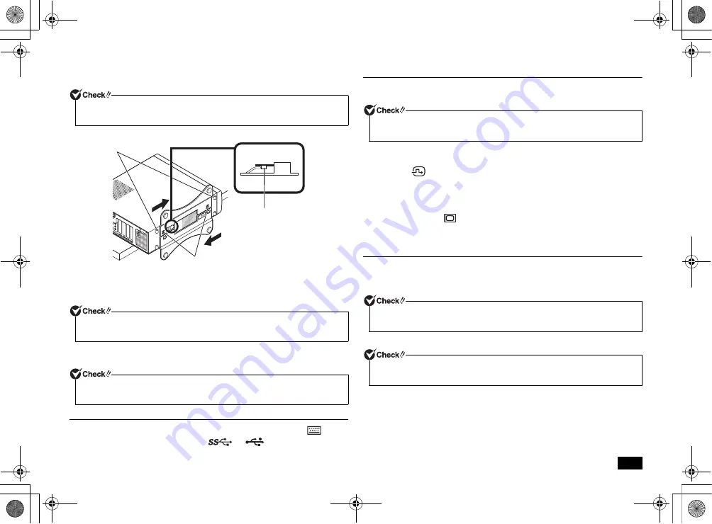
Align the stabilizers with the prongs on the computer and slide the 
stabilizers in the direction of the arrow until the stopper locks.

Attaching one stabilizer

When you place the computer vertically with the right front side facing a wall, attach 
one stabilizer to the left front side of the computer.

1

Attach one stabilizer to the left front side of the computer as described in 
"Attaching two stabilizers" (p.2)

2. Connect the keyboard and the mouse

1

Connect the purple keyboard port to the purple keyboard port (

).

2

Connect the mouse to a USB port (

 or 

).

3

. Connect the display

Connect your display to the computer using either a digital connector or an analog 
connector.

Connecting a digital LCD display

1

Make sure the DVI cable connected to the back of the LCD display matches 

the icon (

) and shape of the computer's DVI-D port, and then attach the 

cable to the computer's DVI-D port and secure it by tightening the screws.

Connecting an analog LCD display

1

Make sure the analog RGB cable connected to the back of the LCD display 
matches the icon (

) and shape of the computer's analog RGB port, and 

then attach the cable to the computer's analog RGB port and secure it by 
tightening the screws.

4. Connect the power cord and the ground wire

1

Insert the power cord plug into an AC wall outlet.

There may be different ways of connection depending on the type of the display.

2

Connect the power cord to the computer.

3

Insert the other end of the power cord into an AC wall outlet.

Please be careful not to hurt your fingers when attaching the stabilizers to the 
computer.

Do not block the air vent located on the left front side of the computer when placed 
near a wall.

When attaching only one stabilizer, please place the opposite side of the computer 
against the wall to ensure that it will not fall down.

Plastic 

feet

Overhead view

Stopper

Prong

If you will use the dual display function on the MB model, connect the display after 
Windows Setup has finished.

If a ground wire is attached to the supplied power cord, connect it to the ground 
terminal of the AC wall outlet.

Although the power may turn on and off after a few seconds, the machine is not 
broken.

NEC_Mate.fm  Page 3  Monday, November 12, 2012  3:39 PM

Summary of Contents for MB

Page 1: ...ific to this computer assuming that the user is able to perform basic Windows operation and understands how to use help in its installed applications to resolve problems In this user s manual unless specified Windows 7 refers to Windows 7 Professional 32 bit with Service Pack 1 SP1 installed System configuration and software installation should be conducted by a user who has administrator privileg...

Page 2: ... Failure to do so may cause damage Connect the LAN cable only after completing Windows setup and firewall configuration This ensures that your computer can be safely connected to a network 1 Attaching the stabilizers This computer includes stabilizers that keep your computer stable when it is stood vertically The stabilizers are not attached to the computer at the time of shipment When you stand t...

Page 3: ...o the back of the LCD display matches the icon and shape of the computer s analog RGB port and then attach the cable to the computer s analog RGB port and secure it by tightening the screws 4 Connect the power cord and the ground wire 1 Insert the power cord plug into an AC wall outlet There may be different ways of connection depending on the type of the display 2 Connect the power cord to the co...

Page 4: ...ur user name and computer name when prompted and click Next to continue 3 Enter a user account password when prompted and click Next to continue 4 Please check the contents when the Please read the license terms page is displayed 5 After checking the contents check I accept the license terms and click Next to continue Important points during setup Preparation for setup For the user name and comput...

Page 5: ...n the left side of the window click Storage Disk Management 5 Select the volume marked as C and right click it 6 Click Shrink Volume 7 Enter the desired size into the Enter the amount of space to shrink in MB box The size entered here will become the maximum size of the newly created partition 8 Click Shrink 9 After shrinking is complete select the unassigned space that has been reserved and right...

Page 6: ... the latest version of Windows installed Windows 7 Service Pack 1 SP1 is pre installed on this computer It is not possible to uninstall Windows 7 Service Pack 1 SP1 Knowing the Parts The front side The back side Creating a system repair disc Windows Update and Microsoft Update Your computer has been delivered to with the all current updates already installed Please do not attempt to uninstall thes...

Page 7: ...es are designed to allow internal heat to escape Please be careful not to leave the air vent blocked 15 Cable stopper Prevents the keyboard cable from pulling out or protects devices connected using cables against theft The cable stopper can be found in the included accessory case 16 Slide stopper Fixes the roof cover firmly 17 LAN port A port used to connect a LAN cable Communication speed LED Li...

Page 8: ...rently accessing data Keyboard LED state Computer State On Green Caps Lock is on all letters are entered as capital letters Off Caps Lock is off all letters are entered as lowercase letters LED state Computer State On Green Scr Lock is on Off Scr Lock is off LED state Computer State On Green Num Lock is on Off Num Lock is off A sensor detects the movement of the mouse with the assistance of the li...

Page 9: ...you to be able to remotely turn your computer s power on or wake it up from sleep or hibernate from an administrator s PC when your computer has a LAN connection The following steps can be used to configure your computer to allow WoL from when the power is turned off 1 Turn on the power and immediately press F2 several times The BIOS setup utility will then be displayed 2 In the Advanced menu sele...

Page 10: ...Covers The roof cover needs to be removed when installing internal devices such as memory or a PCI board 1 Turn off the computer 2 Make sure the power LED is off and then remove the power cord and all cables and cords 3 If you are using a security lock remove it 4 If the computer is placed horizontally proceed to step 7 If the computer is placed vertically place the computer as shown in the follow...

Page 11: ...ide and lift up and remove the cover where it stops Refer to the following procedure when closing the roof cover 1 Attach the roof cover at about 40 mm above the back side of the machine and slide the cover to the back side keeping the roof cover hook and the hole of the machine close Please be careful not to pinch strike or cut your fingers when removing the stabilizers Chassis prong Stopper Stab...

Page 12: ...ity the installation order and the location of the slot This machine has four memory slots and allows a maximum of 8 GB Up to four memory cards can be installed one at a time two memory cards are installed at the time of shipment from the factory Insert the memory in the order of DIMM_A2 DIMM_B2 DIMM_A1 and DIMM_B1 Slot location Please be careful not to pinch strike or cut your fingers when attach...

Page 13: ...nal 32 bit allows a maximum of 4 GB of memory Before installing the board Installing and Removing Installing The PCI board PCI Express x1 board PCI board is very vulnerable to static electricity Touching the PCI board when static electricity is generated in your body may damage the board Before touching the board eliminate static electricity by touching a metal object such as an aluminum sash or d...

Page 14: ... F9 key The message Load Optimized Defaults appears 3 Confirm that Yes is selected and then press Enter This will load the default factory setting values 4 Press the F10 key The message Save configuration and reset appears 5 Confirm that Yes is selected and then press Enter These setting values are saved the BIOS setup utility will finish and your computer will restart Configuration is now complet...

Page 15: ...curity menu select Security Chip Configuration and press Enter 3 Confirm that TPM Support is set to Enabled If it is set to Disabled please change it to Enabled 4 Set Change TPM State to Enable Activate 5 Press the F10 key A confirmation message is displayed 6 Select Yes and then press Enter The settings are saved and the BIOS setup utility exits 7 If a confirmation screen is displayed after the c...

Page 16: ...eting it 3 times However since the data is written 3 times it takes 3 times longer than simple mode for deletion to be completed DoD introduced mode 3 times erasure Verify Deletes data from the hard disk in a method compliant to the U S Department of Defense Standard 00 FF and random value is written in order 3 times and verifies that the final random data is written correctly Effective deletion i...

Page 17: ...ting the process Recovery Disc Before recovery if there is data that you would like to maintain make a backup of the data and then perform recovery Once recovery is performed all the settings including system configuration will be reset to the factory default settings If you would like to use the current settings again after recovery such as BIOS setup utility settings and network settings make a ...

Page 18: ...rformed There are two recovery options Recovery from hard disk and Recovery from DVD 1 Turn on the computer 2 When the NEC logo screen is displayed repeatedly press F11 until the NEC logo screen disappears and Windows is loading files is displayed 3 When Windows 7 32bit Recovery is displayed read the precautions and then press Enter 4 When the Windows Recovery screen is displayed select Start to r...

Page 19: ...ull settings display not included available in the selection menu 28 The 32 bit version of the OS cannot utilize the entire capacity even with 4 GB or more of RAM The usable capacity is approx 3 GB Furthermore depending on the configuration the usable RAM volume may vary Windows Setup When Windows setup has completed turn the power OFF and then do settings to your needs Depending on your usage env...

Page 20: ...product only The included DVD ROM and CD ROM are for use with this product only 7 Distribution and copying all or part of the software without permission of the copyright owner is copyright infringement 8 Hardware maintenance information is saved 9 This product contains the software that does not pass the test of the Designed for Windows program 10 The content in this manual was created at the tim...

Reviews: