52
6.5
Install Overframes and Power bar cover
The Overframes protect the LED Wall from any dust or other particles that could come in through
the holes on the sides and the top.
Inside the Overframes are slot nuts. The Overframes are attached to the LED Wall via screws,
which go through the Cabinet interlock anchors into the slot nuts.
Info
It is easier to install the Overframes first and later the Pixel cards. However, if the Pixel cards
are already installed, only a few Pixel cards need to be taken out to install the Overframes. The
pictures also show the procedure with installed Pixel cards.
This section is a guide through the assembly of the frame and its installation on the LED Wall.
Table 11: Overframe and Power bar cover Installation Requirements
No. of People
2
Prerequisites
Cabinets
Enough space in front of LED Wall to assemble frame
Tools
Screwdriver
Allen key
Service tool
Equipment
Overframes:
Corner frame bottom (left, right)
Overframe (left, right) (LED Wall)
Overframe (top)
Corner frame top (left, right)
Power bar cover
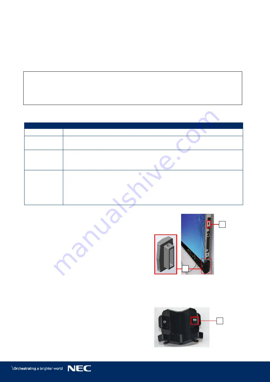
Attach the Corner frame bottom (left, right)
Step 1)
(A) to the Power bar on both sides.
If the Pixel cards are already installed:
Step 2)
Place the Overframes (left, right) next to the
edge of the LED Wall.
With the Service tool (Figure 115, p. 85),
remove those Pixel cards that cover the
Cabinet interlock anchors (B) that connect
to the Overframes (left, right).
You need to have access to the Cabinet
interlock anchors (B) from the inside of the
cabinet.
Figure 58: Installing Corner frame
bottom (left, right)
Before mounting the Overframes on the LED Wall, assemble the frame on the ground
Step 3)
in front of the LED Wall.
Attach the Corner frames top (left, right) to
Step 4)
the Overframe (top) with the pre-installed
screw (D).
Attach the Overframe (left, right) to the
Step 5)
Overframe (top) and Corner frames top
(left, right) with the pre-installed screw (D)
Figure 59: Corner frame top
A
B
D
Summary of Contents for LED-FA025i2-220
Page 61: ...61 Figure 78 Screen Settings for 8 8 Controller...
Page 91: ...91 Part Name AC terminal Hub For 0 9 mm only CAT cable Mask For 1 5 1 9 2 5 3 8 mm only...
Page 96: ...96 LED FA015i2 137 Data Connections 15 1 3 LED FA015i2 137 Power Connections 15 1 4...
Page 97: ...97 LED FA019i2 165 Data Connections 15 1 5 LED FA019i2 165 Power Connections 15 1 6...
Page 99: ...99 LED FA012i2 220 Data Connections 15 1 9 LED FA012i2 220 Power Connections 15 1 10...


