background image

E – 19

WARNING

• Installing your projector on the ceiling must be done by a quali-

fied technician. Contact your NEC dealer for more information.

* Do not attempt to install the projector yourself.
• Only use your projector on a solid, level surface. If the projector

falls to the ground, you can be injured and the projector se-
verely damaged.

• Do not use the projector where temperatures vary greatly. The

projector must be used at temperatures between 32˚F (0˚C)
and 95˚F (35˚C).

• Do not expose the projector to moisture, dust, or smoke. This

will harm the screen image.

• Ensure that you have adequate ventilation around your projec-

tor so heat can dissipate. Do not cover the vents on the side or
the front of the projector.

If your projector is mounted on the ceiling and your image is upside
down, use the “Menu” and “Select” buttons on your projector cabinet or

▲▼

 button on your remote control to correct the orientation. (See page

E-43.)

Reflecting the Image

Using a mirror to reflect your projector’s image enables you to enjoy a
much larger image. Contact your NEC dealer if you need a mirror. If
you’re using a mirror and your image is inverted, use the “Menu” and
“Select” buttons on your projector cabinet or 

▲▼

 buttons on your re-

mote control to correct the orientation. (See page E-43.)

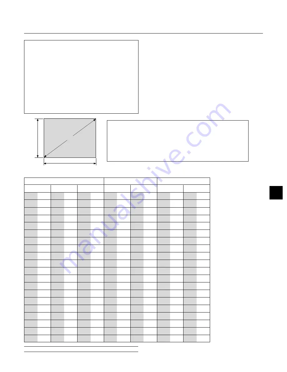
For screen sizes between 25" and 300" not indicated on the above table, use for-
mulas below.

Projection Distance =  

Screen Width (H)

Lens Magnification

Throw distance for Standard Lens (m/inch) =

H

2.0 through H

2.4 (For H between 1.2 m/47 inch and 12.0 m/472 inch)

Throw distance for Long Zoom Lens (m/inch) =

H

3.4 through H

5.1 (For H between 4.1 m/161 inch and 21.0 m/827 inch)

Height

Screen size (Diagonal)

Width

25

30

40

60

67

72

80

84

90

100

120

150

180

200

210

240

250

270

300

0.6

0.8

1.0

1.5

1.7

1.8

2.0

2.1

2.3

2.5

3.0

3.8

4.6

5.1

5.3

6.1

6.4

6.9

7.6

20

24

32

48

54

58

64

67

72

80

96

120

144

160

168

192

200

216

240

0.5

0.6

0.8

1.2

1.4

1.5

1.6

1.7

1.8

2.0

2.4

3.0

3.7

4.1

4.3

4.9

5.1

5.5

6.1

15

18

24

36

40

43

48

50

54

60

72

90

108

120

126

144

150

162

180

0.4

0.5

0.6

0.9

1.0

1.1

1.2

1.3

1.4

1.5

1.8

2.3

2.7

3.0

3.2

3.7

3.8

4.1

4.6

-

47

63

94

106

114

126

130

142

157

189

236

283

315

331

378

394

425

472

-

1.2

1.6

2.4

2.7

2.9

3.2

3.3

3.6

4.0

4.8

6.0

7.2

8.0

8.4

9.6

10.0

10.8

12.0

47

55

75

110

126

134

150

157

169

189

224

283

339

378

398

453

472

-

-

1.2

1.4

1.9

2.8

3.2

3.4

3.8

4.0

4.3

4.8

5.7

7.2

8.6

9.6

10.1

11.5

12.0

-

-

-

-

-

161

181

197

217

228

244

272

327

413

496

551

579

661

689

744

827

-

-

-

4.1

4.6

5.0

5.5

5.8

6.2

6.9

8.3

10.5

12.6

14.0

14.7

16.8

17.5

18.9

21.0

-

-

161

244

272

291

327

343

366

409

492

618

740

823

-

-

-

-

-

-

-

4.1

6.2

6.9

7.4

8.3

8.7

9.3

10.4

12.5

15.7

18.8

20.9

-

-

-

-

-

inch

m

inch

m

inch

m

inch

m

inch

m

inch

m

inch

m

Diagonal

Width

Height

Wide

Tele

Wide

Tele

Screen Size

Standard Lens (2.0-2.4)

Long Zoom Lens (3.4-5.1)

NOTE: 

Distances may vary +/-5%.

Screen and Projection Distance

Summary of Contents for GT950 - MultiSync XGA LCD Projector

Page 1: ...E 1 GT950 LCD Projector User s Manual English S O U R C E S E L E C T L E N S S H I F T F O C U S Z O O M S T A T U S P O W E R O N S T A N D B Y A U T O A D J U S T M E N U E N T E R C A N C E L ...

Page 2: ...cations Commission does not allow any modifications or changes to the unit EXCEPT those specified by NEC Technologies in this manual Failure to comply with this gov ernment regulation could void your right to operate this equip ment This equipment has been tested and found to comply with the limits for a Class B digital device pursuant to Part 15 of the FCC Rules These limits are designed to provi...

Page 3: ...the wall outlet the POWER indicator has not changed to a steady orange glow Immediately after the cooling fan stops working The cooling fan con tinues to work for 2 minutes after the projector is turned off with the POWER button While the POWER and the STATUS indicators are alternately flashing CAUTION To protect the Lens Shift mechanism a hard polyurethane foam pad is attached to the lens Before ...

Page 4: ... Ratio E 40 Noise Reduction E 40 Position Clock E 40 Resolution E 40 Video Filter E 40 Overscan E 40 Factory Default E 41 Color Management E 41 Color Temperature E 41 Gamma Correction E 41 Color Correction E 41 Color Matrix E 41 White Balance E 42 Projector Options E 42 Sleep Timer E 42 Menu E 42 Menu Mode E 42 Advanced Menu Basic Custom Menu E 42 Language E 42 Projector Pointer E 42 Menu Display ...

Page 5: ...ers a crisp image with UXGA 1600 1200 resolu tion 2 Supports most IBM VGA SVGA XGA SXGA UXGA with Advanced AccuBlend 2 Macintosh component signal YCbCr YPbPr or any other RGB signals within a horizontal frequency range of 15 to 100 kHz and a vertical frequency range of 48 to 120 Hz This includes NTSC PAL PAL M PAL N PAL60 SECAM and NTSC4 43 stan dard video signals NOTE Composite video standards ar...

Page 6: ......

Page 7: ... S H I F T F O C U S Z O O M S T A T U S P O W E R O N S T A N D B Y A U T O A D J U S T M E N U E N T E R C A N C E L Getting to Know Your GT950 Projector Remote Sensor Air Filter Lens hood cap Lens Ventilation outlet Carrying Handle Slot for Kensington Micro saver Security System Controls Remote Sensor Front Side Features Remote Sensor Lamp Cover Air Filter Stand attachment portion ...

Page 8: ... IN Rear Side Features AC Input Connect the supplied power cable s three pin plug here Terminal Panel PC Card Slot USB Mouse Terminal Foot Built In Stereo Speaker 2W Remote Sensor Built In Stereo Speaker 2W Remote Sensor Attaching the lens hood cap to the bottom with the supplied string and rivet String Rivet Lens hood cap 1 Thread the string through the hole on the lens hood cap 2 Use the rivet t...

Page 9: ...the lens to the center by going to Projector Options Lens then Zero Position of the menu See Page E 47 To use the remote control for this press the SHIFT button to bring up the Lens Shift display then move the lens to center with the SE LECT buttons Press the CANCEL button to close the dis play See Page E 29 Lens protection spacer Lens hood cap 2 Insert the Supplied Lens Protection Spacer Above an...

Page 10: ...rn the display to the landscape orientation Repeat any one of the three methods above NOTE This driver is for exclusive use with Windows 95 98 Me NT 4 0 2000 and angle of 270 degrees counterclockwise rotation only Left click the Pivot icon on the taskbar and then select Help to get help NOTE See the installation method described in the supplied CD ROM2 for in stallation details See Page E 43 for i...

Page 11: ...ar is not displayed these buttons can be used to select a slide or to move the cursor in Folder List or Slide List When the pointer is displayed these buttons move the pointer Top Features 6 Enter Button Executes your menu selection and activates items selected from the menu 7 Cancel Button Press this button to exit Menus Press this button to return the adjust ments to the last condition while you...

Page 12: ...ap when using the port 5 Video Input Connector RCA Connect a VCR DVD player laser disc player or document camera here to project video 6 Mouse Output Port Mini DIN 8 Pin Use this port to operate your computer s mouse functions from the remote control 7 S Video Input Connector DIN 4 pin Here is where you connect the S Video input from an external source like a VCR 8 Remote Control Input Jack Connec...

Page 13: ...RGB VIDEO S VIDEO or DVI digital analog Output sound level can be adjusted in accordance with the sound level of the internal speaker 15 USB Terminal Connect a commercially available mouse that supports USB You can operate the menu or PC Card Viewer with the USB mouse via this terminal Note that this terminal is not used with a computer and that there may be some brands of USB mouse that the proje...

Page 14: ...selected menu item A press of the button executes the selection When the pointer is displayed these buttons move the pointer 15 ENTER Left Click Button When you are in the Computer mode this button works as the mouse left button When this button is pressed and held for a minimum of 1 5 seconds the drag mode is set When you are in the Projector mode which is indicated by lighting the PJ button Use ...

Page 15: ...s changed to the magnifying icon 25 FREEZE Button This button will freeze a picture Press again to resume motion 26 PICTURE MUTE Button This button turns off the image and sound for a short period of time Press again to restore the image and sound NOTE When the menu is displayed a press of this button mutes an image and sound without turning off the menu 27 VOLUME Button Press to increase the volu...

Page 16: ...es until it snaps into place Do not mix different types of batteries or new and old batteries Remote Control Precautions Handle the remote control carefully If the remote control gets wet wipe it dry immediately Avoid excessive heat and humidity If you will not be using the remote control for a long time remove the batteries Do not place the batteries upside down Do not look into the laser pointer...

Page 17: ...When the PJ button is lit if you want to use the mouse function immediately press the PJ button to return to the Computer mode not lit Works as the Select button on the projector MENU ENTER CANCE L PJ FOCUS ZOOM OFF VIDEO AUTO ADJ S VIDEO RGB1 RGB2 LASER ON VOLUME SHIFT HELP POINTER KEYSTONE MAGNIFY FREEZE PIC MUTE PC CARD SLIDE FOLDER SLIDE LIST SELECT POWER MENU ENTER CANCE L FOCUS ZOOM OFF VIDE...

Page 18: ...elect a non glossy white wall onto which you can project your image 3 Connect the supplied power cable 4 Set up the projector 5 Connect a PC VCR DVD player or other equipment 6 Make setting or adjustments on the projector Selecting a Location The further your projector is from the screen or wall the larger the image The minimum size the image can be is approximately 25 0 64 m measured diagonally w...

Page 19: ...ted on the above table use for mulas below Projection Distance Screen Width H Lens Magnification Throw distance for Standard Lens m inch H 2 0 through H 2 4 For H between 1 2 m 47 inch and 12 0 m 472 inch Throw distance for Long Zoom Lens m inch H 3 4 through H 5 1 For H between 4 1 m 161 inch and 21 0 m 827 inch Height Screen size Diagonal Width 25 30 40 60 67 72 80 84 90 100 120 150 180 200 210 ...

Page 20: ...ifted in two directions combined maximum range in either direction cannot be obtained due to rounded off area near edge of lens ex ample shift up and right See diagram below Lens Shift Range for Desktop and Ceiling Mount Application The diagram below shows the location of the image position in the lens The lens can be shifted within the shaded area as shown using the normal projection position as ...

Page 21: ...e projector and the notebook PC before turning on the power to the notebook PC In most cases signal cannot be output from RGB output unless the notebook PC is turned on after connecting with the projector NOTE If using video S video or audio cables the cables should be 3 m 9 8 feet or shorter Remote Control Guideline 1 Plug the supplied serial cable with the mouse output port of the projector into...

Page 22: ... it may be caused by a screen saver installed on the computer you ve connected to the projector IBM VGA or Compatibles Notebook type or Macintosh Notebook type Audio cable not supplied RGB signal cable supplied To mini D Sub 15 pin connector on the projector It is recommended that you use a commercially available distribution amplifier if connecting a signal cable longer than the supplied one IBM ...

Page 23: ...mouse and connect the supplied serial cable from the mouse output to your PC s mouse port Use the 6 pin adapter for connecting to a PS 2 computer or the supplied USB adapter For Macintosh Attach the supplied mouse adapter for USB to the mouse output port s serial cable and connect the projector to your USB port of a Macintosh computer 3 When the built in remote mouse receiver is available it will ...

Page 24: ...h connector sizes of 39 mm x 16 mm 1 53 x 0 63 or less to keep the two connectors from making contact with each other Connecting a PC with DVI output The DVI input accepts up to the XGA 60Hz signal NOTE The Auto Adjust feature does not work for DVI digital signal When DVI signal is selected and the image position is not corrected adjust the horizontal and vertical position using the Position Clock...

Page 25: ... component video Y Cb Cr output use a commercially available component video cable RCA 3 and the optional 15 pin to RCA female 3 cable to connect your DVD player to the RGB INPUT connector on the projector For a DVD player without component video Y Cb Cr outputs use common RCA cables not provided to connect a composite VIDEO output of the DVD player to the Video Input of the projector 3 Turn on th...

Page 26: ... these connections simply 1 Turn off the power to the projector and VCR laser disc player or document camera 2 Connect one end of your RCA cable to the video output connector on the back of your VCR or laser disc player connect the other end to the Video input on your projector Use an audio cable not supplied to connect the audio from your VCR or laser disc player to your audio equipment if your V...

Page 27: ...re See page E 45 NOTE Immediately after turning on the projector screen flicker may occur This is not a fault Wait 3 to 5 minutes until the lamp lighting is stabilized Indicators POWER STATUS POWER STATUS POWER STATUS POWER STATUS OFF ON POWER SELECT LENS SHIFT FOCUS ZOOM STATUS POWER ON STAND BY UTO ADJUST MEN U E N T E R CANCEL AC IN AUDIO INPU AUDIO INPU AUDIO OUTP AUDIO OUTPUT DVI I INPUT RGB ...

Page 28: ...MAGNIFY FREEZE PIC MUTE PC CARD SLIDE FOLDER SLIDE LIST SELECT POWER About Startup Screen Menu Language Select screen When you first turn on the projector you will get the Startup screen This screen gives you the opportunity to select one of the seven menu languages English German French Italian Spanish Swedish and Japa nese To select a menu language follow these steps 1 Use the Select or button t...

Page 29: ...ess the CANCEL button See page E 20 for Lens Shift Adjustable Range Projected image position can be shifted by using the LENS SHIFT button on the cabinet Pressing two arrow buttons at the same time can move the lens diago nally 2 Press the ZOOM button to display the Zoom adjustment screen Use the Select button on the remote control to adjust the image size To close the Zoom adjustment screen press...

Page 30: ...djustment Rotate the four feet to make the image square to the screen Up Down Each of the feet height can be changed up to 0 24 6mm or at angles up to 1 8 degrees AUDIO IN AUDIO IN AUDIO OU AUDIO OUT DVI IN RGB IN RGB OUT PC CONTROL MOUSE OUTPUT REMOTE CONTROL INPUT AUDIO IN AUDIO IN R L MONO VIDEO S VIDEO ...

Page 31: ...tion adjusts the clock fre quencies that eliminate the horizontal banding in the image This func tion also adjusts the clock phase to reduce video noise dot interfer ence or cross talk This is evident when part of your image appears to be shimmering This adjustment may be necessary when you connect your computer for the first time NOTE The Auto Adjust function does not work for component signal Ba...

Page 32: ...play Help Exit Help Using Pointer You can use one of eight pointers to draw your audience s attention to the portion of a projected image you want Press the Pointer button to display the pointer Use the Select button to move the pointer Enlarging and Moving a Picture You can enlarge the area you want up to 400 percent To do so 1 Press the Pointer button to display the pointer 2 Move the pointer to...

Page 33: ...our needs 1 Select Basic Custom Menu Edit to display the Basic Custom Menu Edit screen Using the Menus NOTE The on screen menu may not be displayed correctly while interlaced motion video image is projected 1 Press the Menu button on the remote control or projector cabi net to display the Main Menu NOTE When using a USB mouse click the mouse button to display the main menu For other operations do ...

Page 34: ... the Passcode input screen will be displayed See page E 48 for more information 2 Use the or button to highlight your selection and press the Enter button to place a check mark next to an option This action enables that feature Press the Enter button again to clear the check box If you select an item with a solid triangle and press the Enter button on the remote control or the projector cabinet yo...

Page 35: ...ition Clock Resolution Video Filter Overscan Input Signal 1 33 1 1 78 1 1 85 1 2 35 1 Display Area 1 33 1 1 78 1 1 85 1 2 35 1 Off Low Medium High Horizontal Vertical Clock Phase Auto Native On Off 0 5 10 25 Normal Natural 1 Natural 2 Off Mode 1 Mode 2 Mode 3 sRGB User 1 User 2 Select Color Matrix HDTV SDTV Select Color Matrix Type B Y R Y Cb Cr Pb Pr Brightness R G B Contrast R G B Keystone Lamp ...

Page 36: ...5 Page 6 Orientation Desktop Front Ceiling Rear Desktop Rear Ceiling Front Portrait Auto Off On Background Blue Black Logo Mouse Button Right Hand Left Hand Sensitivity Fast Medium Slow PC Card Viewer Options Show Folder List Auto Play Manual Play Interval 5 300 sec Capture Options High Quality Normal High Compression Signal Select RGB Auto RGB Component Scart Video Auto NTSC3 58 NTSC4 43 PAL PAL ...

Page 37: ...icates settings or the direction of adjustment OK button Press to confirm your setting You will return to the previous menu Cancel button Press to cancel your setting You will return to the previous menu Close button Click to close the window with saving changes USB mouse only Help button Indicates that help about that feature is available USB mouse only Press the Help button on the remote control...

Page 38: ...nent signal Video Selects what is connected to your Video input VCR laser disc player DVD player or document camera S Video Selects what is connected to your S Video input VCR DVD player or laser disc player NOTE A frame may freeze for a brief period of time when a video is played back in fast forward or fast rewind with a Video or S Video source A press of the MENU button displays the toolbar a p...

Page 39: ...um keystone angle that can be corrected is 30 degrees up ward and 30 degrees downward with the projector placed horizontally on the ground plane Depending on the type of graphics being used the picture may get blurred or keystone correction may not be possible when excessive keystone correction is used The idea is the closer you are to native resolution the better image you will see Lamp Mode This...

Page 40: ...ment is made auto matically when the Auto Adjust is turned on Phase Use this item to adjust the clock phase or to reduce video noise dot interference or cross talk This is evident when part of your image appears to be shimmering Use the and buttons to adjust the image Position Clock when Auto Adjust is off This allows you to activate or deactivate the Advanced AccuBlend fea ture Auto Turns on the ...

Page 41: ...is recommended for Normal For the regular picture Natural 1 For true color reproduction of natural tones Natural 2 For dark portions of a picture Color Correction This option allows you to adjust neutral tint for yellow cyan or ma genta There are 4 factory presets optimized for various types of images or you can set 2 user adjustable settings Color Correction OFF Turns off the Color Correction You...

Page 42: ...jector Pointer This enables you to select from eight different Pointer icons for the Pointer button on your remote control After moving your Pointer icon to the area you want on the screen press the Magnify button on the remote control to enlarge the se lected area on the screen See page E 32 for more details Menu Projector Options White Balance This allows you to adjust the white balance Brightne...

Page 43: ...cape ap propriate for the projector orientation Off Setting for the landscape orientation NOTE Be sure not to select this option when using the projector in the portrait orientation because the temperature control setting will vary de pending upon between the portrait or landscape setting On Setting for the portrait orientation Background Use this feature to display a blue black screen or logo whe...

Page 44: ...tions are used for the Capture function that you can select from Tools You have three options for JPEG compression quality High quality Normal and High Compression High Quality Gives quality of JPEG a priority Normal Gives normal JPEG quality High Compression Gives compression a priority Page2 PC Card Viewer Options Page3 Signal Select RGB and DVI ANALOG Allows you to choose RGB for an RGB source ...

Page 45: ...essage is displayed you must be in the Projector mode to operate your projector using the remote control If not press the PJ button on the remote control to change your projector to the Projector mode The button lights to indicate that you are in the Projector mode Keystone Save This option enables you to save your current keystone settings Saving your change once affects all sources The changes a...

Page 46: ...hecking this box will make the set default route valid When data is sent from the LAN card the transfer location will be searched according to the previously set routing information however when the transfer location has not been found as a result of the search the data will be sent to the device that holds the IP address set here The IP address that is set here must be one that can be identified ...

Page 47: ...This option selects two speed modes for lens shift Normal This is the default setting that allows the lens shift motor to run fast Fine This is the fine adjustment setting that allows the lens shift motor to run slowly Zero Position Returns the lens position to the default setting Select Zero Position and press the ENTER button Next select OK and press the ENTER button To cancel select CANCEL and ...

Page 48: ... to move the tool bar for USB mouse operation only Capture Captures an image and save it as a JPEG file in a PC card Freeze Freezes and unfreezes images Exit Exits the Capture function Unless a PC card is inserted into the PC Card slot of the projector the Capture feature is not available The Card Error display means that the free space of the PC card is insufficient for saving images Make more sp...

Page 49: ... to return to the PC Card Files screen Drag Drags to move the tool bar for USB mouse operation only Return Returns to the PC Card Files screen Close Close the toolbar Changing Background Logo The Logo button allows you to select a background logo from graphic files on a PC card and change to it as the background logo NOTE File size must be 64KB or less Other file formats than JPEG and BMP are not ...

Page 50: ...the complete drawing and exits the ChalkBoard NOTE The ChalkBoard feature is available only when a USB mouse is used Free hand drawings cannot be saved or captured The menu is not available while you display the ChalkBoard screen The Capture function is not available on ChalkBoard screen Switching slides clears a drawing completely Contents Provides an online help about how to use the menus An und...

Page 51: ...PC Card Viewer PPT Converter 1 0 Add In Version converts files created with Microsoft PowerPoint 95 97 2000 hereafter referred to as PowerPoint into indexes playable with PC Card Viewer Microsoft Windows and PowerPoint are registered trademarks of Microsoft Corporation Inserting and Ejecting a PC Card A PC card is used to view presentation data prepared on the computer and to capture and play imag...

Page 52: ...56 Starting Up the PC Card Viewer Software on your PC PC Card Viewer Utility 1 0 Use the PC Card Viewer Utility 1 0 for creating viewer slides To start the PC Card Viewer software Select Start Programs NEC Projector Tools PC Card Viewer Utility 1 0 Refer to online help for instructions on using the PC Card Viewer soft ware Contents of the English version PC Card Viewer software PC Card Viewer Util...

Page 53: ...r Options of the menu This allows you to move on to the next slide when Manual Play is selected Stop This allows you to stop Auto Play while you are playing back and to resume playing from the selected slide or folder when Auto Play is selected Jump Displays a list of slides while you are playing back Select Displays a list of folders while you are playing back Setup Displays the PC Card Viewer Op...

Page 54: ...oving pictures from a VCR etc it is possible to switch from a PC Card Viewer slide to the video picture then back to the PC Card Viewer slide simply by using a source button and PC CARD button NOTE Even if you switch the current PC Card Viewer source to another source the current slide is retained When you return back to the PC Card Viewer you will get the slide that has been retained NOTE The PC ...

Page 55: ... PC card data is damaged use a computer to repair the data NOTE The folder in the right bottom is always a folder exclusively for captured images To display the list of folders when there are 13 or more indexes stored on the PC card select Edit index from the PC Card Viewer software s File menu and move the index you want to display to within 12 indexes from the top of the folder index For details...

Page 56: ...e software Use the procedure described below to uninstall the PC Card Viewer software files 1 From the Start menu select Settings then Control Panels 2 In the Control Panels dialog box double click on Add Remove Programs 3 In the Add Remove Programs Properties dialog box click the Setup Remove tab then select PC CardViewer Utility 1 0 from the list of applications and click on Add Remove 4 In the ...

Page 57: ...TA specifications It is one fourth the volume of a PCMCIA card PCMCIA 2 1 PC cards are divided into three types according to their thickness Type I 3 3 mm Type II 5 0 mm and Type III 10 5 mm A type of image format The standard Windows Bit Map format used for MS DOS Windows compatible computers A type of image format JPEG is the abbreviation of Joint Photographic Experts Group JPEG compression offe...

Page 58: ... If this happens contact your NEC dealer for lamp replacement To replace the lamp 1 Loosen the lamp cover screw until the screwdriver goes into a freewheeling condition and remove the lamp cover The lamp cover screw is not removable 4 MAINTENANCE 2 Loosen the two screws securing the lamp housing until the screw driver goes into a freewheeling condition The two screws are not removable Remove the l...

Page 59: ...E SELECT LENS SHIFT FOCUS ZOOM STATUS POWER ON STAND BY AUTO ADJUST MEN U E N T E R CANCEL 2 Reinstall the new filter cover NOTE Do not detach the sponge from the filter cover Do not wash the filter cover with soap and water Soap and water will damage the the filter mem brane Before replacing the filter cover remove dust and dirt from the pro jector cabinet Keep out dust and during filter replacem...

Page 60: ...screen See page E 30 Use the Keystone to correct the trapezoid distortion See page E 33 or 39 Adjust the focus See page E 29 Reposition the projector to improve its angle to the screen See page E 30 Ensure that the distance between the projector and screen is within the adjustment range of the lens See page E 19 Use menus or a source button on the remote control or the cabinet to select the source...

Page 61: ...destroyed While an image with over 1024 768 dots is projected several lines of information will be lost Use the supplied software change the image to 1024 768 dots in size Use a computer etc to repair the data Condition Status When using the PC Card Viewer function For more information contact your dealer No picture Part of a slide is not displayed Contents of PC Card are damaged ...

Page 62: ...M PAL N NTSC4 43 YCbCr 350 TV lines SECAM RGB 1024 dots horizontal 768 dots vertical Power Requirement 100 120 200 240 VAC 50 60 Hz Input Current 3 4 A 100 120 VAC 1 7A 200 240 VAC Mechanical Dimensions 14 3 W 6 4 H 12 7 D 362mm W 163mm H 323mm D not including lens and feet Net Weight 15 9 lbs 7 2 kg Environmental Considerations Operational Temperatures 32 95 F 0 to 35 C 20 80 humidity Storage Tem...

Page 63: ...NS SHIFT FOCUS ZOOM STATUS POWER ON STAND BY AUTO ADJUST M E N U E N T E R C A N C E L 88 8 3 50 168 2 6 62 163 6 42 323 12 72 189 7 44 362 14 25 1 0 04 Cabinet Dimensions Unit mm inch Lens position center Lens position center ...

Page 64: ...e Cb 4 Ground 5 Ground 6 Red Ground Cr Ground 7 Green Ground Y Ground 8 Blue Ground Cb Ground 9 No Connection 10 Sync Signal Ground 11 Ground 12 Bi directional DATA SDA 13 Horizontal Sync or Composite Sync 14 Vertical Sync 15 Data Clock Signal Level Video signal 0 7Vp p Analog Sync signal TTL level 5 1 4 2 3 10 11 12 13 14 15 6 9 7 8 ...

Page 65: ...080p 1080i 1080i 1080i 1080p 350 400 400 480 480 480 480 600 600 600 600 600 768 768 768 768 864 960 1024 1024 1024 1200 1200 1200 1200 480 624 768 870 1024 1024 1024 900 1024 768 900 1024 Signal Name Resolution H V Horizontal Frequency Vertical Frequency 15 734 15 625 31 5 45 0 33 75 28 13 33 72 28 13 33 75 26 97 26 97 31 5 37 9 37 0 31 5 37 9 37 5 43 3 35 2 37 9 48 1 46 9 53 7 48 4 56 5 60 0 68 ...

Page 66: ... PICTURE MUTE OFF 02H 11H 00H 00H 00H 13H SOUND MUTE ON 02H 12H 00H 00H 00H 14H SOUND MUTE OFF 02H 13H 00H 00H 00H 15H ON SCREEN MUTE ON 02H 14H 00H 00H 00H 16H ON SCREEN MUTE OFF 02H 15H 00H 00H 00H 17H NOTE Contact your local dealer for a full list of the PC Control Codes if needed Cable Connection Communication Protocol Baud rate 38400 bps Data length 8 bits Parity No parity Stop bit One bit X ...

Reviews: