background image

Warnings and Additions to This Document 


Express5800/R120h-2M (2nd-Gen) User’s Guide 

17


Using a computer extensively may affect different parts of your body. Here are tips you should follow while working on 
a computer to minimize strain on your body. 
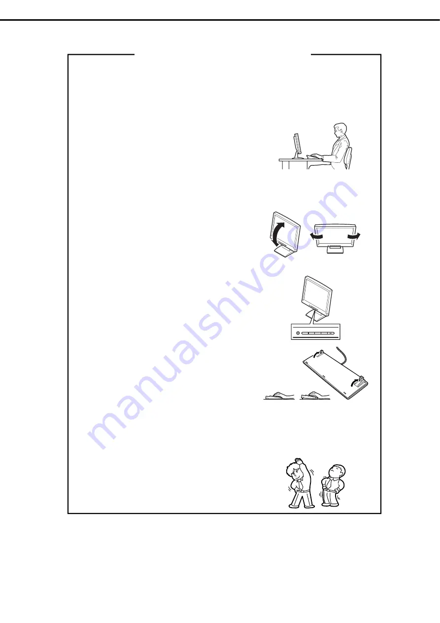
 

Keep proper posture 

The basic body position for using a computer is sitting straight with 
your hands on the keyboard parallel with the floor, and your eyes 
directed slightly downward toward the monitor. With the proper 
posture described above, no unnecessary strain is applied on any 
part of your body, in other words when your muscles are most 
relaxed. 
Working on the computer with bad posture such as hunching over or 
being too close to the monitor could cause fatigue or deteriorated 
eyesight. 


Adjust the angle of your display 

Most display units are designed for adjustment of the horizontal and 
vertical angles. This adjustment is important to prevent the screen 
from reflecting bright lights and to make the display contents easy to 
see. Working without adjusting the display to a comfortable angle 
makes it difficult for you to maintain a proper posture and you will get 
tired easily. Adjust the viewing angle before use. 


Adjust the brightness and contrast of the display 

Display screens have functions to control brightness and contrast. 
The most suitable brightness/contrast depends on age, individuals, 
and environment, so adjust it to suit your preferences. A too bright or 
too dark display is bad for your eyes. 


Adjust the angle of keyboard 

Some keyboards are ergonomically designed, which allow the angle 
to be adjusted. Adjusting the angle of the keyboard is effective to 
reduce tension on your shoulders, arms, and fingers. 


Clean your equipment 

Keeping your equipment clean is important not only for the appearance but also for functional and safety reasons. A 
dusty monitor makes it difficult to see the display contents, so clean it regularly. 

Take rest breaks 

When you feel tired, take a break. Light exercise is also 
recommended. 


Tips for your health and safety


Summary of Contents for EXP805

Page 1: ...erver Express5800 Series Express5800 R120h 2M 2nd Gen EXP805 N8100 2775F 2776F 2777F 2778F Chapter 1 General Description Chapter 2 Preparations Chapter 3 Setup Chapter 4 Appendix 10 201 02 101 01 May...

Page 2: ...options connection of peripheral devices and suitable location for this server Chapter 3 Setup System utility configurations and summary of EXPRESSBUILDER Chapter 4 Appendix Specifications and other...

Page 3: ...operations 16 Chapter 1 General Description 18 1 Introduction 19 2 Accessories 20 3 Features 21 4 Names and Functions of Parts 25 4 1 Front View With Front Bezel 25 4 2 Front View Without Front Bezel...

Page 4: ...heat sink 70 Handling precautions 70 Installation 70 Identifying processor type 74 Removal 74 1 11 DIMM 75 Maximum supported memory size 75 DIMM installation order 76 Memory processor compatibility in...

Page 5: ...he Tertiary Riser Drive Cage N8154 95 163 Removal 167 1 28 3x 3 5 inch Rear Drive Cage N8154 99 168 Installation 168 Removal 170 1 29 4x 3 5 inch Mid plane Drive Cage N8154 100 171 Installation 171 Re...

Page 6: ...4 Cases that Require Configuration 235 2 5 Management of RBSU Settings of System Utilities via Networks 239 Overview 239 How to Backup RBSU 240 How to Restore RBSU 241 Notes 242 3 iLO 5 243 3 1 Overv...

Page 7: ...s symbol indicates the presence of a hazard if the instruction is ignored An image in the symbol illustrates the hazard type Prohibited Action This symbol indicates prohibited actions An image in the...

Page 8: ...is server Optical disk drive This server is equipped with one of the following drives These drives are referred to as optical disk drive in this document DVD ROM drive DVD Super MULTI drive Hard disk...

Page 9: ...7 Server Red Hat Enterprise Linux 7 Server x86_64 Abbreviations of Operating Systems VMware VMware Operating Systems are referred to as follows Notations in this document Official names of VMware ESXi...

Page 10: ...ks of Microsoft Corporation in the United States and other countries Intel and Xeon are registered trademarks of Intel Corporation of the United States Vmware is a registered trademark or a trademark...

Page 11: ...NESS FOR A PARTICULAR PURPOSE ARE DISCLAIMED IN NO EVENT SHALL THE COPYRIGHT HOLDER OR CONTRIBUTORS BE LIABLE FOR ANY DIRECT INDIRECT INCIDENTAL SPECIAL EXEMPLARY OR CONSEQUENTIAL DAMAGES INCLUDING BU...

Page 12: ...nd or the Unified Extensible Firmware Interface UEFI Forum s UEFI Specifications v 2 0 and later together the UEFI Specifications only as necessary to emulate an implementation of the UEFI Specificati...

Page 13: ...roduct includes software developed by Greg Roelofs and contributors for the book PNG The Definitive Guide published by O Reilly and Associates zlib End User License Agreement zlib License zlib h inter...

Page 14: ...4 NEC Corporation assumes no responsibility for effects resulting from your operations The sample values used in this document are not actual values Keep this document for future use Latest editions...

Page 15: ...arning label Warning label are attached on or near the components with potential hazards This label is either attached or printed on the component Do not remove or black out this label and keep it cle...

Page 16: ...OST completes Turn off the server and unplug the power cord before moving it Regularly clean the server to prevent various types of failure See Chapter 1 Maintenance 2 Daily Maintenance in Maintenance...

Page 17: ...screen from reflecting bright lights and to make the display contents easy to see Working without adjusting the display to a comfortable angle makes it difficult for you to maintain a proper posture a...

Page 18: ...This chapter introduces the features of this server and the name of each part 1 Introduction 2 Accessories Describes the accessories of the server 3 Features Describes the features of the server and t...

Page 19: ...y the latest microprocessor Intel Xeon processor With our latest technology and architecture we offer high performance and high reliability that could not be accomplished by conventional servers Furth...

Page 20: ...attached to Front Bezel Safety Precautions and Regulatory Notices Getting Started In addition to these enclosed items the following extra items may be required Operating system or application software...

Page 21: ...DP 125W DDR4 2933 1TB Xeon Gold 6230 Processor 2 10 GHz 20C 40T TDP 125W DDR4 2933 1TB Xeon Gold 6234 Processor 3 40 GHz 8C 16T TDP 130W DDR4 2933 1TB Xeon Gold 6238 Processor 2 10GHz 22C 44T TDP 140W...

Page 22: ...100BASE TX 10BASE T interface 10Gbps 1Gbps 100Mbps 10Mbps supported can be selected High reliability Processor throttle ring feature Memory monitoring feature error correction error detection Memory x...

Page 23: ...multi processor system with up to two processors Expansion Bay for hard disk drives up to 30 slots 10 Optical disk drive bay provided as standard 8x 3 5 inch drive model USB3 0 interface Front 1 port...

Page 24: ...acquired 80 PLUS Titanium Power supply units N8181 159 160 162 acquired 80 PLUS Platinum 7 When an optional riser card is installed with PCI Express 3 0 2 slot x16 lanes for the primary riser PCI Expr...

Page 25: ...Names and Functions of Parts This section describes the names of the server parts 4 1 Front View With Front Bezel 1 Front Bezel A cover for protecting the front of the server This cover can be locked...

Page 26: ...2 5 inch drive model Universal media bay 24 x 2 5 inch drive model 8 x 3 5 inch drive model 1 3 4 1 9 2 2 2 1 2 3 2 7 2 5 2 4 2 6 2 8 5 6 7 8 3 4 9 2 18 2 17 2 19 2 23 2 21 2 20 2 22 2 24 5 6 7 8 2 1...

Page 27: ...remote management of iLO or firmware update the UID LED lights up or flashes if iLO is restarted via UID switch 7 iLO service port USB connector A USB connector used for connecting to iLO such as for...

Page 28: ...for showing the status of LAN See page 41 10 LAN connectors 1 Connectors for connecting to a network 1000BASE T 100BASE TX 10BASE T 10 1 LAN1 connector 10 2 LAN2 connector 10 3 LAN3 connector 10 4 LA...

Page 29: ...4 Names and Functions of Parts Express5800 R120h 2M 2nd Gen User s Guide 29 Chapter 1 General Description 4 4 External View 1 Top cover 2 Hood latch 1 2...

Page 30: ...der the heat sink 1 CPU1 required option 2 CPU2 option 4 DIMM option 5 Slot for RAID Controller 6 Motherboard 7 Primary Riser Card Standard riser is standard installed Changeable by option 8 Secondary...

Page 31: ...or for optical disk drive 12 Power supply SW USB 3 0 connector 13 Battery connector for RAID controller 14 Power Connector for Expander Board 15 Power Connector for Expander Board 16 Power connector f...

Page 32: ...Reserved Important Do not change the system maintenance switch that says Reserved unless it is instructed by the document It may cause the trouble or malfunction of the device 1 Set the SW1 to ON whe...

Page 33: ...not recommended to let is operate without the necessary fans installed and running The following displays the structure for installing cooling fans Configuration Fan bay 1 Fan bay 2 Fan bay 3 Fan bay...

Page 34: ...fan setting to Increased Cooling in System Utilities Maintenance Guide Common Chapter 1 Useful Features 1 System Utilities 1 2 2 BIOS Platform Configuration RBSU 12 Advanced Options Menu a Fan and The...

Page 35: ...ng Lights off The network is not working 4 UID switch LED 1 Do not reboot the iLO from the boot of the server until the completion of the OS boot and during using the System Utilities Lights in blue W...

Page 36: ...s not working 4 UID Switch LED 1 Do not reboot the iLO from the boot of the server until the completion of the OS boot and during using the System Utilities Lights in blue Working in operation Flashes...

Page 37: ...ng Lights off The network is not working 3 STATUS LED 1 Lights in green Normal state Flashes in green once per second Restarting iLO Flashes in amber The function of the system is deteriorating 3 Flas...

Page 38: ...LED The following table shows a list on power failure LEDs and affected subsystems Not all power failures are applied on all servers Subsystem LED status Motherboard Flashes once Processor Flashes twi...

Page 39: ...Lights off Normal state Lights in amber The power subsystem is degraded the power supply unit has failed or the input power is disconnected Riser Card LED Lights off Normal state Amber Riser card unit...

Page 40: ...r card unit is not properly installed Cooling Fan LED Amber Amber Green One cooling fan has failed or has been removed Amber Red Green Two or more cooling fans have failed or have been removed Power S...

Page 41: ...ights in green Working in operation Flashes in green Working in operation Lights off Not working 4 left AC POWER2 LED Lights in green Normal state Lights off One or more of the following situations ar...

Page 42: ...US LED Lights in green A drive is a member of one or more logical drives Flashes in green Rebuilding the drive migrating RAID on the drive migrating or expanding the capacity of the strip size expandi...

Page 43: ...0 R120h 2M 2nd Gen User s Guide 43 Chapter 1 General Description Optical Disk Drive Access LED optional The LED for optical disk drive at the front of the server flashes when a CD or DVD is being acce...

Page 44: ...h 2M 2nd Gen User s Guide 44 Chapter 1 General Description 4 9 Identification of Drive Boxes Front BOX Chart number BOX number 1 BOX1 2 BOX2 3 BOX3 Chart number BOX number 1 BOX1 2 BOX2 3 BOX3 Rear BO...

Page 45: ...4 Names and Functions of Parts Express5800 R120h 2M 2nd Gen User s Guide 45 Chapter 1 General Description Chart number BOX number 1 BOX4 2 BOX6 Mid BOX Chart number BOX number 1 BOX7...

Page 46: ...er Controller Connection to a on board SATA port Connection to a PCI board AROC Type a to be installed on a dedicated connector for RAID controller Connection to a RAID controller PCI board Type p to...

Page 47: ...4 Names and Functions of Parts Express5800 R120h 2M 2nd Gen User s Guide 47 Chapter 1 General Description Front Mid...

Page 48: ...number 5 8 SAS Expander Port 5 connection Drive bay number 9 12 SAS Expander Port 6 connection Drive bay number 13 16 SAS Expander Port 7 connection Drive bay number 17 20 SAS Expander Port 8 connect...

Page 49: ...nctions of Parts Express5800 R120h 2M 2nd Gen User s Guide 49 Chapter 1 General Description In the case of 12x 3 5 inch drive middle 4x 3 5 inch drive rear 2x2 5 inch drive cages x3 Mid Rear 2 5 inch...

Page 50: ...eparations This chapter describes preparations for using this server 1 Installing Internal Optional Devices You can skip this section if you did not purchase any optional devices 2 Installation and Co...

Page 51: ...and safely WARNING Be sure to observe the following precautions to use the server safety Failure to observe the precautions may cause death or serious injury For details see Safety Precautions and Re...

Page 52: ...nents Beware of high temperatures Do not get your fingers caught when installing components If the server is mounted on a rack use the UID switch to identify the target server See Chapter 2 1 3 Identi...

Page 53: ...Disk Drives in the RAID System Attach the air baffle See Chapter 2 1 33 Attaching the air baffle Attach Top Cover See Chapter 2 1 34 Installing Top Cover Mount the server onto the rack See Chapter 2 2...

Page 54: ...When the server is working be sure to identify the target server by using UID Switch first before you turn off the server or disconnect a cable from the server To turn UID LED on press UID Switch When...

Page 55: ...he right and unlock the lever seen on the left when you face the front bezel and pull only the left side of bezel by about 10 cm toward you Then as shown in the diagram pull the bezel to the left forw...

Page 56: ...hexalobular driver T 10 or flathead driver See steps 1 to 5 in Chapter 2 1 2 Overview of Installation and Removal for preparations Unscrew the security screw with the hexalobular driver or flathead dr...

Page 57: ...hs of time with the top cover air baffle expansion slot cover or the blank cover removed If the server operates under these conditions it will not be properly ventilated and the cooling mechanism will...

Page 58: ...the TPM is bound to the system board If an OS is configured to use the TPM and it is removed the OS may go into recovery mode data loss can occur or both When installing or replacing hardware our ser...

Page 59: ...shut off system power Portions of the power supply and some internal circuitry remain active until AC power is removed Important To reduce the risk of personal injury from hot surfaces allow the drive...

Page 60: ...ent device the data including the key stored in TPM are deleted when the power is turned on the TPM that has been removed from the original server and installed on another server 5 Installing the TPM...

Page 61: ...details on how to adjust the TPM Kit used for BitLocker visit the Microsoft website Notes on Windows BitLocker The recovery key password is generated during BitLocker setup and can be saved and print...

Page 62: ...umber Important To avoid static electricity see Chapter 1 1 8 Anti static Measures in Safety Precautions and Regulatory Notices Make sure to use the CPU authorized by NEC Installing a third party CPU...

Page 63: ...ESXi 6 7 768 112 1 When Hyper V is used the maximum number of logical processors is as shown below Windows Server 2012 R2 320 Windows Server 2016 512 Windows Server 2019 512 Installation Please prepar...

Page 64: ...hten each heatsink nut in the order indicated on the heatsink label 1 2 3 4 until it no longer turns 4 If installing a second processor install fans in bays 1 and 2 These fans are provided with the pr...

Page 65: ...6 Install an additional fan unit provided with additional CPU kit Remove the fan blank cover from the fan bay 7 Attach the fan to bay 1 and 2 Fan connection conditions are shown in the table below Fan...

Page 66: ...on the POST To view this information and additional processor specifications follow the directions below 1 Reboot the server The server restarts and the POST screen is displayed 2 Press F9 key System...

Page 67: ...r these conditions poorly controlled airflow and cooling will make it to overheat and cause damage Note In order to prevent the damage to electronic components please start to install the system after...

Page 68: ...tach the top cover of the server Note In order to prevent damage of the system due to improper cooling or elevated temperature please do not activate the server or enclosure without implementing any o...

Page 69: ...e required for redundancy If the cooling fan fails or lacks the redundancy will fail High performance fans may be necessary in 8 x 2 5 inch configuration and 8 x 3 5 inch configuration for the followi...

Page 70: ...lling the option Parts included in the optional processor heat sink kit T 30 hexalobular driver 1 4 flat blade screwdriver or nonconductive tool To install the components follow these steps 1 Please f...

Page 71: ...2 3 4 Note Contacts on the motherboard are very fragile and easily damaged To avoid damage to the motherboard do not touch the processor or processor socket contact 3 Lift the processor heat sink mod...

Page 72: ...ing corners of the processor assembly 5 Separate the processor assembly from the heatsink The processor remains attached to the carrier 6 Using alcohol remove thermal grease adhering to the processor...

Page 73: ...1 indicator on the processor carrier and the socket Align the processor heatsink assembly with the heatsink alignment pins and gently lower it down until it sits evenly on the socket The heatsink alig...

Page 74: ...manual to conduct installation and connection and turn the power supply ON Identifying processor type The type of processor installed on the server is displayed simply on the POST To view this inform...

Page 75: ...information corresponding to all the types all the types are referred to as DIMM If you specify LRDIMM or RDIMM the information is applicable only to the type It is necessary that the type of all of...

Page 76: ...2 CPU PROC1 PROC2 configuration When only CPU1 is mounted DIMM slot number 1 2 3 4 5 6 7 8 9 10 11 12 DIMM Mounted number and installation 1 DIMM 1 2 DIMM 1 2 3 DIMM 1 2 3 4 DIMM 4 3 1 2 5 DIMM 5 4 1...

Page 77: ...2 10 22 8 20 14 2 16 4 18 6 11 9 21 7 19 13 1 15 3 17 5 23 DIMM 12 10 22 8 20 14 2 16 4 18 6 11 23 9 21 7 19 13 1 15 3 17 5 24 DIMM 12 24 10 22 8 20 14 2 16 4 18 6 11 23 9 21 7 19 13 1 15 3 17 5 Impor...

Page 78: ...222 processor 2667MHz Xeon Silver 4200 Series 2400MHz Xeon Bronze 3200 Series 2133MHz The operation memory speed is decided by rating DIMM speed DIMM attached on each channel processor model and speed...

Page 79: ...tion Meaning 1 Capacity 8GB 16GB 32GB 64GB 128GB 2 Rank 1R Single rank 2R Dual rank 4R Quad rank 8R Octal rank 3 DRAM data width X4 4 bit X8 8 bit X16 16 bit 4 Memory generation DDR4 5 The maximum spe...

Page 80: ...ally closes Important Make sure the orientation of the DIMM The DIMM has a notch preventing being incorrectly inserted Do not apply too much pressure when you push a DIMM into the slot Doing so can da...

Page 81: ...he trouble shooting on a malfunctioning DIMM or the information on LEDs see 4 Status LED Panel combined LED descriptions Removal Replacement To replace or remove DIMM follow these steps To remove DIMM...

Page 82: ...ion against uncorrectable memory errors than provided by Advanced ECC The Memory Mirroring function and Memory Sparing function create redundancy by monitoring and switching memory between memory chan...

Page 83: ...1 Installing Internal Optional Devices Express5800 R120h 2M 2nd Gen User s Guide 83 Chapter 2 Preparations Memory Controller 1 Memory Controller 2 Memory Controller 1 Memory Controller 2 PROC1 PROC2...

Page 84: ...to 1 System Utilities in Chapter 1 of Maintenance Guide Common Important Single rank DIMMs do not support the Memory Mirroring function The followings are the conditions to use this function Install...

Page 85: ...sor Notes for the setting of memory mirroring Even if Mirrored Memory with Advanced ECC Support is set in Advanced Memory Protection and Memory Mirroring Configuration is selected in case DIMM configu...

Page 86: ...DIMM installed and the capacity per one For the physical memory capacity available from the operating system refer to the table below The number of CPU The number of memory Types of on board memory 8...

Page 87: ...he spare set Memory sparing between different memory channels Note When using Memory Mirroring Function install 12 DIMMs per CPU Use memories with the same product number for the device Notes for the...

Page 88: ...the total number of RANK for each channel is 2 or higher When using the memory ADDDC function install DIMM 8 or DIMM 12 per CPU DIMM with the practicable ADDDC function is N8102 724 N8102 723 N8102 72...

Page 89: ...n installing or removing a riser card Do not touch the terminals of the riser cards and the leads of electronic components with your bare hand Fingerprints and dust left on them cause the server to ma...

Page 90: ...the top of riser card turn the screws to the right 180 degrees while pressing them down Then after fixing the riser card put down the screw handles as before 4 See Chapter 2 1 34 Installing Top Cover...

Page 91: ...o install the components follow these steps 1 See steps 1 to 6 in Chapter 2 1 2 Overview of Installation and Removal for preparations 2 Unfasten two screws securing the rear blank cover and pull up th...

Page 92: ...n and connection and turn the power supply ON Installing Tertiary Riser Card Please prepare the following before installing the options Parts included in the option kit T 10 hexalobular driver Note In...

Page 93: ...e secondary riser card 4 Attach the secondary riser card removed in step 3 to secondary side of tertiary riser card butterfly riser card and fasten with 3 screws After that proceed to step 6 5 Remove...

Page 94: ...Chapter 2 Preparations 6 Remove the 3 screws that fix the tertiary riser blank cover in place and remove the cover by lifting it up Note Keep each removed blank covers 7 Take out a rear blank from the...

Page 95: ...nal positions 9 See Chapter 2 1 34 Installing Top Cover to attach the top cover of the server Note In order to prevent damage of the system due to improper cooling or elevated temperature please do no...

Page 96: ...harge if appropriate grounding wire treatment is not conducted Please prepare the following before installing the options Parts included in the option kit M 2 media If expanding Phillips screwdriver T...

Page 97: ...the right 180 degrees while pressing them down Then after fixing the riser card put down the screw handles as before 6 See Chapter 2 1 34 Installing Top Cover to attach the top cover of the server No...

Page 98: ...or the expansion board please remove all the AC power cables before removing installing riser card All slots support full height PCI cards Use the PCI card length according to the table below Primary...

Page 99: ...x16 x8 x16 x8 x16 x8 x16 x8 Slot size Dedic ated to RAID Dedic ated to LOM FH FH FH FH FH FH FH FH FH FH FH FH FH FH FH Available size FL FL HL HL HL HL FL FL HL HL HL HL FL FL HL N8103 189 RAID Contr...

Page 100: ...2 4 6 7 8 N8104 184 Dual Port 10GBASE T Adapter PCI Express 3 0 x4 1 3 5 2 4 6 7 8 N8104 187 Dual port 25GBASE SFP28 Adapter SFP28 2ch 1 3 5 2 4 6 7 8 N8104 183 Dual Port 10GBASE T Adapter PCI Expres...

Page 101: ...ce 1 Slot form 2 Slot size Slot performa nce 1 Slot form 2 Slot size M 2 SATA SSD slot GPU power connector N8116 56 x16 x16 FH FL x16 x16 FH HL N8116 62 x8 x8 FH FL x16 x16 FH HL x8 x8 FH HL Supported...

Page 102: ...completely by the power button on the front panel Until the AC power cord is unplugged the power supply circuit is still active in some parts of the machine Note When running a server always ensure p...

Page 103: ...lectric parts installed on the board Installing boards with dirt or oil can cause malfunction Note Make sure that the edge of a PCI card bracket is seated into the fixed slot of the riser card unit De...

Page 104: ...right 180 degrees to fix the cage Then put down the screw handle as before 7 See Chapter 2 1 34 Installing Top Cover to attach the top cover of the server Note In order to prevent damage of the system...

Page 105: ...ver baffle expansion slot cover and blank If the server supports components with hot plug support minimize the amount of time the top cover is open Please prepare the following before installing the o...

Page 106: ...t 7 Fit the terminal of riser card to the slot on the mother board and insert the terminal firmly into the slot Then fix the riser card Next raise the screw handle at the top of cage and turn the hand...

Page 107: ...wire treatment is not conducted Installing RAID Controller Please prepare the following before installing the option Parts included in the option kit To install the components follow these steps 1 Mak...

Page 108: ...ser card to direction 1 and remove the blank cover by pulling it out to direction 2 Note Keep each removed blank covers 5 Fit properly the terminal parts of PCI board to the connector of riser card an...

Page 109: ...to the slot on the mother board and insert the terminal firmly into the slot Then fix the riser card Next raise the screw handle at the top of cage and turn the handle to the right 180 degrees to fix...

Page 110: ...improper cooling or elevated temperature please do not activate the server or enclosure without implementing any of component or blank on all of drive bays and device bays 11 Please see Chapter 2 2 In...

Page 111: ...ssibility of causing electrostatic discharge if appropriate grounding wire treatment is not conducted Installation Please prepare the following before installing the option Parts included in the optio...

Page 112: ...ling Top Cover to attach the top cover of the server Note In order to prevent damage of the system due to improper cooling or elevated temperature please do not activate the server or enclosure withou...

Page 113: ...9803 001 X4 Mini SAS cable Port 1 Port 1 Group B From SAS Expander to front 2 5 inch drive cage Cable Description Connection to SAS Expander Connection to Drive BOX 776402 001 X4 Mini SAS cable Port 3...

Page 114: ...the options Parts included in the option kit To install the components follow these steps 1 See steps 1 to 7 in Chapter 2 1 2 Overview of Installation and Removal for preparations 2 Remove the fan cag...

Page 115: ...he cover to direction 2 Then remove the blank cover of Slot 3 Note Keep each removed blank covers 5 Properly insert the SAS Expander Card port component into the riser card connector and close it by s...

Page 116: ...y into the slot Then fix the riser card Next raise the screw handle at the top of cage and turn the handle to the right 180 degrees to fix the cage Then put down the screw handle as before 7 Confirm i...

Page 117: ...onnecting the PCI board Type p exclusively for the RAID controller and the SAS expander 8 Connect the SAS expander and the backplanes of the various drive cages Connecting the backplane of the 2 5 inc...

Page 118: ...Chapter 2 Preparations Connecting the backplane of the 2 5 inch drive BOX 1 BOX 2 BOX 3 and the SAS expander Connecting the backplane of the rear primary 2 5 inch drive cage and the SAS expander Conn...

Page 119: ...e 119 Chapter 2 Preparations Connecting the backplane of the rear tertiary 2 5 inch drive cage and the SAS expander Connecting the backplane of the rear 3x3 5 inch drive cage and the SAS expander Conn...

Page 120: ...rations 9 Remove all the fans from the fan cage to the state where only the fan cage is left Next align the fan cage with the device push the cage slowly from the above direction and tilt both sides o...

Page 121: ...damage of the system due to improper cooling or elevated temperature please do not activate the server or enclosure without implementing any of component or blank on all of drive bays and device bays...

Page 122: ...utions and Regulatory Notices Installation Please prepare the following before installing the option Parts included in the option kit T 30 hexalobular driver T 10 hexalobular driver Option high perfor...

Page 123: ...configuration 4 Install the high performance heat sink See Chapter 2 1 10 High performance CPU heat sink module N8101 1286 1U heat sink 5 Attach the air baffle See Chapter 2 1 33 Attaching the air baf...

Page 124: ...se the part in the direction of 3 9 Connect a power cable from the GPU to a power connector on the riser 10 Slide the retaining clip to the unlock side 11 Align the terminal part of the riser card wit...

Page 125: ...ling or elevated temperature please do not activate the server or enclosure without implementing any of component or blank on all of drive bays and device bays 14 Please see Chapter 2 2 Installation a...

Page 126: ...1 1 8 Anti static Measures in Safety Precautions and Regulatory Notices Installation Please prepare the following before installing the option Parts included in the option kit T 10 hexalobular driver...

Page 127: ...dles as before 7 See Chapter 2 1 34 Installing Top Cover to attach the top cover of the server Note In order to prevent damage of the system due to improper cooling or elevated temperature please do n...

Page 128: ...Flash Backup Unit is an extremely sensitive device Prior to installation avoid static electricity by touching the metal frame of the unit or similar Do not drop or otherwise damage Flash Backup Unit F...

Page 129: ...1 Installing Internal Optional Devices Express5800 R120h 2M 2nd Gen User s Guide 129 Chapter 2 Preparations 3 Remove the fan cage 4 Install Flash Backup Unit 5 Connect the cable...

Page 130: ...rations 6 Remove all the fans from the fan cage to the state where only the fan cage is left Next align the fan cage with the device push the cage slowly from the above direction and tilt both sides o...

Page 131: ...system due to improper cooling or elevated temperature please do not activate the server or enclosure without implementing any of component or blank on all of drive bays and device bays 11 Please see...

Page 132: ...able to install and boot VMware ESXi Notes N8106 016 2x8GB microSD card installing kit USB is equipped with RAID1 function The function cannot be installed with M 2 SATA SSD This product does not inc...

Page 133: ...Insert USB flash memory into the connector Removal When removing practice the steps of installing reversely When you operate the device without components install the blank cover that was installed on...

Page 134: ...please start to install the system after conducting the appropriate anti static treatment There is a possibility of causing electrostatic discharge if appropriate grounding wire treatment is not condu...

Page 135: ...es from the front and insert the universal media bay unit and fix it in place using the 2 screws 6 If installing the optional optical disk drive remove the optical disk drive blank cover The blank cov...

Page 136: ...the front to the universal media bay and fix it in place with a screw 8 Connect cables Connect the Displayport cable to the Displayport connector Connect the USB cable to the front dual internal USB 3...

Page 137: ...rations 9 Remove all the fans from the fan cage to the state where only the fan cage is left Next align the fan cage with the device push the cage slowly from the above direction and tilt both sides o...

Page 138: ...t damage of the system due to improper cooling or elevated temperature please do not activate the server or enclosure without implementing any of component or blank on all of drive bays and device bay...

Page 139: ...er earth is not provided electrostatic discharge may occur Before installing the option prepare the followings Parts included in the option kit T 10 hexalobular driver DVD ROM drive N8151 137 or DVD D...

Page 140: ...by pushing out the right end of it from the inside to the outside or pulling it out 7 Insert the optical disk drive from the front and fix it with a screw 8 Insert the module attached with the optical...

Page 141: ...uide 141 Chapter 2 Preparations Connect the power switch module cable to the connector Connect Displayport cable to the connector Connect the optical disk drive cable to the connector SATA5 Power swit...

Page 142: ...2 Preparations 10 Install the fan cage Rmove all the fans from the fan cage and confirm no fan is installed in the cage Next fit the fan cage to the device push the cage slowly from above and lower t...

Page 143: ...improper cooling or an elevated temperature do not operate the server or the enclosure without installing any of component or blank on all the drive bays and device bays 13 Execute the installation an...

Page 144: ...install the system after conducting the appropriate anti static treatment There is a possibility of causing electrostatic discharge if appropriate grounding wire treatment is not conducted Please prep...

Page 145: ...er s Guide 145 Chapter 2 Preparations 3 Unfasten the screws x2 of the bay blank cover and pull the blank cover forward to remove it BOX2 Note Keep each removed blank covers 4 Insert the 8x 2 5 inch dr...

Page 146: ...press5800 R120h 2M 2nd Gen User s Guide 146 Chapter 2 Preparations 5 Connect the power cable of 8x 2 5 inch drive cage BOX2 Single power cable 6 The drive bay data cables are connected as follows BOX2...

Page 147: ...rations 7 Remove all the fans from the fan cage to the state where only the fan cage is left Next align the fan cage with the device push the cage slowly from the above direction and tilt both sides o...

Page 148: ...damage of the system due to improper cooling or elevated temperature please do not activate the server or enclosure without implementing any of component or blank on all of drive bays and device bays...

Page 149: ...s a possibility of causing electrostatic discharge if appropriate grounding wire treatment is not conducted Please prepare the following before installing the options Parts included in the option kit...

Page 150: ...cover and remove the cover pulling it out forward Note Keep each removed blank covers 5 Unfasten the screws x3 securing the optical disk drive tray and draw out and remove the tray from the back of th...

Page 151: ...ach the 2x 2 5 inch drive bay to the universal media bay and secure it with the screws x4 8 Insert and attach the optical disc drive tray in the universal media bay from behind and secure it with the...

Page 152: ...152 Chapter 2 Preparations 10 Connect the drive bay power cable to the power connector on the motherboard 11 Connect the drive bay data cables to the inputs below Connecting to the SAS expander for th...

Page 153: ...ations 12 Remove all the fans from the fan cage to the state where only the fan cage is left Next align the fan cage with the device push the cage slowly from the above direction and tilt both sides o...

Page 154: ...t damage of the system due to improper cooling or elevated temperature please do not activate the server or enclosure without implementing any of component or blank on all of drive bays and device bay...

Page 155: ...c parts start the installation of system after providing proper anti static treatment If a proper earth is not provided electrostatic discharge may occur Before installing the option prepare the follo...

Page 156: ...ard you to dismantle it 5 Insert a front 2x 2 5 inch drive cage N8154 96 or N8118 317 from the front and fix them with two screws 6 Connect the power cable of a front 2x 2 5 inch drive cage N8154 96 o...

Page 157: ...ting to SAS SATA drive cage N8154 96 and RAID controller Connecting to SAS SATA drive cage N8154 96 and SAS expander 8 Remove all the fans from the fan cage and confirm no fan is installed in the cage...

Page 158: ...1 Installing Internal Optional Devices Express5800 R120h 2M 2nd Gen User s Guide 158 Chapter 2 Preparations 9 Push the fan from above to mount it on the fan cage 10 Reinstall all the fans you removed...

Page 159: ...he drive bays and device bays 13 Execute the installation and connection referring to Chapter 2 2 Installation and connection of this book and then turn the power on Removal When removing practice the...

Page 160: ...nt damage unplug the power cord and ensure no power is supplied to the server You cannot turn off the system power supply completely by the power button on the front panel Until the AC power cord is u...

Page 161: ...Raise the screw handles at the top of the primary riser card and turn them to the left 180 degrees Then hold both sides of cage and lift them upright to remove the cage 4 In case of secondary riser un...

Page 162: ...nto the slot Then fix the riser card Next raise the screw handle at the top of the cage and turn the handle to the right 180 degrees to fix the cage Then put down the screw handle as before 7 Connect...

Page 163: ...he Tertiary Riser Drive Cage N8154 95 Important To prevent personal injury electrical shock or equipment damage unplug the power cord and ensure no power is supplied to the server You cannot turn off...

Page 164: ...raise the screw handle at the top of the riser card turn it 180 degrees to the left hold the both ends of the cage and lift it straight up to remove it 3 Unfasten the screws x3 securing the tertiary b...

Page 165: ...ews x4 6 Attach a drive or a dummy tray to the drive cage 7 If you removed a riser card in the step2 fit the terminal of riser card to the slot on the mother board and insert the terminal firmly into...

Page 166: ...d Gen User s Guide 166 Chapter 2 Preparations 8 Connect the power cord between drive backplane and motherboard In case of 12x 3 5 inch drive configuration and power single cable connection In case of...

Page 167: ...er to prevent damage of the system due to improper cooling or elevated temperature please do not activate the server or enclosure without implementing any of component or blank on all of drive bays an...

Page 168: ...lling this option the 12x 3 5 inch drive must be fully installed in the front bay In addition a high performance fan should be installed To install the components follow these steps 1 Back up all data...

Page 169: ...e screws x3 securing the tertiary riser blank cover and pull the cover upward to remove it 5 Attach a rubber bush on a slotted hole on the bottom of the 3 x 3 5 drive cage install the cage from the to...

Page 170: ...ystem due to improper cooling or elevated temperature please do not activate the server or enclosure without implementing any of component or blank on all of drive bays and device bays 10 Please see C...

Page 171: ...re installing the options Parts included in the option kit The option must be attached under the following conditions A 1U heat sink is required to attach this option Attach the 1U heat sink before at...

Page 172: ...he motherboard 4 Lift up the latch of the drive cage 5 Install the drive cage Note Do not drop the drive cage onto the motherboard Dropping the drive cage onto the motherboard may damage the motherboa...

Page 173: ...e plunger pin on the back right of the mid plane drive cage and slowly lower the mid plane drive cage until it interlocks with the plunger pin The mid plane drive cage is attached in this manner 6 Mou...

Page 174: ...erver Note In order to prevent damage of the system due to improper cooling or elevated temperature please do not activate the server or enclosure without implementing any of component or blank on all...

Page 175: ...ponents please start to install the system after conducting the appropriate anti static treatment There is a possibility of causing electrostatic discharge if appropriate grounding wire treatment is n...

Page 176: ...s connected to the cable and pull the module towards you to remove it Do not lose the T 10 screw as it necessary for attachment 4 Route the cables through the openings on the front side of the server...

Page 177: ...rations 6 Remove all the fans from the fan cage to the state where only the fan cage is left Next align the fan cage with the device push the cage slowly from the above direction and tilt both sides o...

Page 178: ...damage of the system due to improper cooling or elevated temperature please do not activate the server or enclosure without implementing any of component or blank on all of drive bays and device bays...

Page 179: ...install the system after conducting the appropriate anti static treatment There is a possibility of causing electrostatic discharge if appropriate grounding wire treatment is not conducted Installati...

Page 180: ...ial blank cover as shown below 3 Install the serial cable A If a tertiary riser is not attached 1 Position the serial cable as shown below 2 Attach the serial cable connector 3 Secure the external con...

Page 181: ...prevent damage of the system due to improper cooling or elevated temperature please do not activate the server or enclosure without implementing any of component or blank on all of drive bays and dev...

Page 182: ...hen building a RAID System The number of hard disk drives required varies in each RAID level If the optional RAID Controller N8103 189 195 is used the RAID System cannot be built in RAID5 RAID6 RAID50...

Page 183: ...pter 2 Preparations 1 33 Attaching the air baffle The procedure for removal is the reverse of installation Important Keep the air baffle close to the device when attaching it so the cables are not pul...

Page 184: ...thead driver Leave the hood latch open and place the top cover straight on the unit so that it is securely inserted in the frame Adjust the position of the top cover so that it protrudes approximately...

Page 185: ...isk drives of different types and or rotational frequencies cannot be used together When performing RAID constructions use hard disk drives of the same capacity type and rotational frequency within th...

Page 186: ...ve model SAS SATA HDD 8x 3 5 inch drive model SAS SATA HDD 2x2 5 SAS SATA HDD SSD PCIeSSD 12x 3 5 inch drive model SAS SATA HDD 4x 3 5 SAS SATA HDD 3 5 inch drive model rear 2x2 5 SAS SATA HDD SSD 3x3...

Page 187: ...SSD 24x2 5 inch drive model rear 2x2 5 SAS SATA HDD SSD 12x 3 5 inch drive model SAS SATA HDD 12 x 3 5 inch drive model Mid plane Drive SAS SATA HDD 12x 3 5 inch drive model rear SAS SATA HDD SAS Exp...

Page 188: ...each Disk Array 1 See Chapter 2 1 2 Overview of Installation and Removal for preparations Locate the slot where you install the hard disk drive Install hard disk drives in ascending order of port numb...

Page 189: ...should be installed for server operation If the server supports the hot pluggable components please minimize the opening time of the top cover 1 Check the drive status via definition of the drive LED...

Page 190: ...same capacity Make sure that the two power supply units have the same part number and the same label color If the two power supply units are inappropriate the system may become unstable to be shut dow...

Page 191: ...power cords When the power cord is connected the AC power LED on the power unit will turn green Power on the server Confirm by STATUS LED or on POST screen that there are no errors related to the pow...

Page 192: ...e the LED AC power LED is off Power off the server Tips In the redundant power configuration with two power supply units and if either one of power supply units fails the failing power supply unit can...

Page 193: ...ecome unstable to be shut down Note In order to prevent damage of the system due to improper cooling or elevated temperature please do not activate the server or enclosure without implementing any of...

Page 194: ...tional Devices Express5800 R120h 2M 2nd Gen User s Guide 194 Chapter 2 Preparations 3 Remove the screw and remove the ground wire terminal 4 Attach the ground wire green to the terminal 5 Remove the t...

Page 195: ...crews on the terminal block connector 7 Connect the ground wire attached to the contact in Step 4 to the power supply unit DC with the screw as shown below Important Make sure to connect it before con...

Page 196: ...Similarly insert the return line DC into the right slot of the terminal block connector and tighten the screw 10 After inserting the 2 lines to the terminal block connector connect it to the power su...

Page 197: ...unit DC illuminate Express5800 R120h 1M Rear side 15 Power on the server 16 Confirm by STATUS LED or on POST screen that there are no errors related to the power supply units See Chapter 2 1 IML Error...

Page 198: ...m the front view of the front bezel into a recess on the front part of the device push the left side lever to the right set in place the left side of the device and then release the lever so that it w...

Page 199: ...n the specified environment Do not connect the ground wire to a gas pipe CAUTION Be sure to observe the following precautions to use the server safely Failure to observe the precautions may cause burn...

Page 200: ...the outlet of another device with large power consumption Place near equipment that generates power noise e g contact spark at power on power off of commercial power supply through a relay Environment...

Page 201: ...that the manufacturer s TMRA specification is not exceeded Power requirements The installation of this equipment must be performed by a qualified electrician according to the electrical standards of...

Page 202: ...NEC and IEC 60950 1 Second edition The standard for Safety of Information Technology Equipment Connect the equipment to the secondary circuit power supply that is properly grounded The secondary circ...

Page 203: ...ool to attach the ring tongue to the power cord wire Important The ring terminal must conform to UL certified 12 gauge Important The minimum nominal diameter for the sled of pillar or stud type termin...

Page 204: ...ecautions to use the server safely Failure to observe the precautions may cause burns injury and property damage For details refer to Safety Precautions and Regulatory Notices Do not drop Do not leave...

Page 205: ...nch drive model N8143 130 Slide Rail Kit for 2U 3 5inch Server Ball bearing type rack rail for 3 5 inch drive model no inner rail used N8143 134 Tool free Slide Rail Kit for 2U 3 5inch Server Slide ra...

Page 206: ...uter rail RIGHT to the right Slide the inner rail to the rear side of the unit in accordance with the four protrusions on the side of the unit At this time check whether the lock located around the ce...

Page 207: ...he same way Make sure that the rail is installed at the same height as the other rail already installed Important Confirm that the rail are securely locked so that they will not fall off Tips Although...

Page 208: ...e outer rails Check the direction of the outer rail Since there are markings of Right and Left on the outer rail check the proper directions of right and left with it Likewise check the directions of...

Page 209: ...tant Confirm that the rail are securely locked so that they will not fall off Tips Although the rail may be somewhat unsteady it is not defective Removing the outer rails Remove outer rails from the r...

Page 210: ...n Express5800 R120h 2M 2nd Gen User s Guide 210 Chapter 2 Preparations 4 Push and release the unlocking lever on the rear side of the outer rail toward the outside of the rack and push the rail backwa...

Page 211: ...rver with single person Do not drop Do not leave the server being pulled out Do not install with the cover removed Do not get your fingers caught 1 Tool free Slide Rail Kit for 2U N8143 133 134 a Inst...

Page 212: ...included cable tie strip to the rear side of the rack attach the tie strip to the mounting hole of the outer rail as shown below 4 If you like to secure the unit to the rack with screw open the lid of...

Page 213: ...Remove the front bezel Open the lids of the unit fixing screws on both sides of the device Then remove the fixing screws inside with Hexalobular screwdriver if the device is screwed on If the device...

Page 214: ...re Important Always install the server with two or more persons 1 Pull out the left and right outer rails until they are completely locked to the front side 2 Hold the unit securely by two or more per...

Page 215: ...secure the unit to the rack with screw open the lid of the edge part of the unit and fasten the Hexalobular screw inside with a Hexalobular screwdriver to secure the unit to the rack b Removal procedu...

Page 216: ...216 Chapter 2 Preparations Open the lids of the unit fixing screws on both sides of the device Then remove the fixing screws inside with Hexalobular screwdriver if the device is screwed on If the dev...

Page 217: ...the stopper button on the side of the rail and lift the device above the rails in the order of 1 2 3 4 to remove it from the rail Important Be careful not to get your fingers caught in the rails or le...

Page 218: ...ause death or serious injury For details refer to Safety Precautions and Regulatory Notices Do not hold the power plug with wet hands Do not connect the ground wire to a gas pipe CAUTION Be sure to ob...

Page 219: ...sed line FRONT Data LAN Ports REAR Device with serial interface USB device Display unit Hub switching hub etc Finally connect the provided power cord to an outlet For connecting with UPS refer to the...

Page 220: ...with the UPS When the power cord is connected to a UPS change the settings from System Utility in order to link the server with the power supply from the UPS To change the settings select System Confi...

Page 221: ...nagement arm A cable management arm can be installed to the unit for combining the multiple cables connected to the device Install the cable management arm in the following steps 1 Attach the power co...

Page 222: ...Express5800 R120h 2M 2nd Gen User s Guide 222 Chapter 2 Preparations 3 Put multiple cables in the binding belt and secure them 4 Insert the fixed parts of the supplied cable management arm into the ou...

Page 223: ...moving the cable management arm 1 Press the lock release button on the fixed part of the cable management arm to release the lock and pull it out forward 2 Press the lock release button on the two fix...

Page 224: ...tion 2 Description on system utility Describes how to set up the system 3 iLO 5 Describes iLO 5 installed in the unit 4 EXPRESSBUILDER and Starter Pack EXPRESSBUILDER helps you to install Windows and...

Page 225: ...ptible power supply UPS make sure that the power supply control unit is turned ON Remove Front Bezel When the STATUS lamp flashes green once per second wait until the lamp lights in steady state Press...

Page 226: ...1 Turning on the Server Express5800 R120h 2M 2nd Gen User s Guide 226 Chapter 3 Setup 8 x 3 5 inch drive model 12 x 3 5 inch drive model Power switch Power switch...

Page 227: ...and an initialization message is displayed The message to tell initialization of a memory and a PCI device Note While the initialization messages are being displayed the screen may change several time...

Page 228: ...attached to each option board Necessary key inputs are different depending on option boards installed so you are requested to operate according to messages 4 The OS starts when POST is completed Tips...

Page 229: ...ion Selection of Primary Boot Controller Configuration of Memory Option Selection of language Start of pre boot environment such as built in UEFI shell or EXPRESSBUILDER Regarding the details of Syste...

Page 230: ...reboot the server To save your change in System Utility and exit press F12 Key F12 Save and Exit In case you cancel your change and exit press ESC Key Exit Tips To put the setting back to the default...

Page 231: ...ntly selected key key Change the value parameter of the selected item You cannot use this key when a menu which has on the left is selected Enter key Press this key to determine the selected parameter...

Page 232: ...ystem Utility Press Esc key to go back to the original screen F7 key The following screen is displayed To put the parameters of System Utility back to the default setting select Restore Defaults and R...

Page 233: ...elect Reboot the device restarts Operation for a restart of iLO in BMC Configuration Utility of System Utilities When saving settings after a setting change in BMC Configuration Utility of System Util...

Page 234: ...inking in green once per second indicates that iLO is being restarted The STATUS lamp illuminating in green indicates that the restart of iLO is completed and it is operating normally 6 After checking...

Page 235: ...RBSU Workload Profile At the time of shipment Workload Profile is set to Custom Set to No C states at System Configuration BIOS Platform Configuration RBSU Power and Performance Options Minimum Proce...

Page 236: ...The following OSs are applicable Red Hat Enterprise Linux 7 x86_64 Windows Server 2012 R2 Windows Server 2016 Windows Server 2019 VMware ESXi6 5 VMware ESXi6 7 The setting must be done in compliance w...

Page 237: ...Use Wake on LAN WOL Set Enabled Disabled in a and b below The setting of b is not reflected when Embedded LOM is used a System Configuration Network Device MBA Configuration Menu or NIC Configuration...

Page 238: ...to Enabled to start OS You may not be able to change TPM Support and TXT Support In that case execute F7 Load Defaults UPS Powerlink When the server is supplied with power from UPS always turn on the...

Page 239: ...ned OFF While POST Immediately after POST Important The Serial Number and Product ID are device specific information Make a note of them and store it in a safe place Tips After completion of POST exec...

Page 240: ...password which are required to log in are written on a slide tag attached to the controlled server 4 Execute types command and confirm the parameter on whose lead Bios is displayed 5 Select BIOS in s...

Page 241: ...function of select command specify the parameter you confirmed in step 4 6 Execute load command to restore RBSU you backed up As the argument of select command specify the parameter you confirmed in s...

Page 242: ...uct ID by referring to Serial Number and Product ID are lost in 5 11 Supplementary notes in 5 Troubleshooting in Chapter 1 of Maintenance Guide The following menus and menus under them cannot be backe...

Page 243: ...lth System Log AHS Log Download Active Health System Log In case the support is needed AHS Log file may need to be sent to NEC or taken by maintenance staff iLO Cooperative Network Management By using...

Page 244: ...only Pre OS only Global Team Collaboration by 6 server administrators at the maximum via IRC Recording and playback of video via IRC Recording and playback of Virtual Serial Port Remote Console of te...

Page 245: ...wser Run POST following Chapter 3 1 1 1 POST sequence After a while the following message is displayed on the lower part of the screen Press the F9 key while the message is being displayed to launch S...

Page 246: ...mple when Network Options is selected On the next screen use DHCP Set DHCP item to Enable or set the item under IP Address Subnet Mask Connect a LAN cable to a management specialized LAN connector to...

Page 247: ...ion Change password without fail at the time of initial setup If you use the initial password unchanged and then you suffer unauthorized access we will not hold any responsibility at all Even if you c...

Page 248: ...all SPP automatically when installing OS SPP must be installed after installing OS Application installation Installs NEC ESMPRO RESTful Interface Tool and other applications Manuals Stores manuals for...

Page 249: ...tware Components Express5800 R120h 2M 2nd Gen User s Guide 249 Chapter 3 Setup 5 Installing Software Components Continue to install software components such as OS See the instructions below Installati...

Page 250: ...of the following methods Press and release the POWER switch This method shuts down applications and OS in the correct order before the server enters standby mode Press and hold the POWER switch for 4...

Page 251: ...Express5800 R120h 2M 2nd Gen User s Guide 251 NEC Express5800 Series Express5800 R120h 2M Appendix 1 Specifications 2 Glossary 3 Revision Record...

Page 252: ...uilt in 2 5 inch HDD SATA 48TB 24x 2TB SAS 57 6TB 24x 2 4TB 2 5 inch SSD SATA SSD 92 16TB 24x 3 84TB SAS SSD 23 04TB 24 960GB When an optional HDD cage is added 2 5 inch HDD SATA 60TB 30x 2TB SAS 72TB...

Page 253: ...to be selected AC Power Unit N8181 161 800W 80 PLUS Titanium power supply unit Outlet with two pole parallel earth Hot plug able Max 2 AC200 240V 10 50 60Hz 3Hz Power cable type needs to be selected...

Page 254: ...Gold 6234 Processor 3 40 GHz 8C 16T TDP 130W DDR4 2933 1TB Xeon Gold 6238 Processor 2 10GHz 22C 44T TDP 140W DDR4 2933 1TB Xeon Gold 6240 Processor 2 60 GHz 18C 36T TDP 150W DDR4 2933 1TB Xeon Gold 6...

Page 255: ...ibed from T1 to T100 This is sometimes abbreviated as 6lobe iLO A built in controller that supports the IPMI version 2 0 protocol The controller is called as iLO5 because this server adopts a generati...

Page 256: ...des SPP instruction manual application and other software for the server This must be installed before using OS on the server Starter Pack is provided as an optional product and ISO data on our websit...

Page 257: ...3 Revision Record Express5800 R120h 2M 2nd Gen User s Guide 257 Chapter 4 Appendix 3 Revision Record Document Number Date Issued Description 10 201 02 101 01 May 2019 Newly created...

Page 258: ...0h 2M 2nd Gen User s Guide May 2019 NEC Corporation 7 1 Shiba 5 Chome Minato Ku Tokyo 108 8001 Japan NEC Corporation 2019 The contents of this manual may not be copied or altered without the prior wri...

Reviews: