


3. BMC/CMC
Express5800/D120h User’s Guide
111
Chapter 3 Setup
3.2
BMC/CMC Network Configuration
For details of the network settings of BMC/CMC, see “BMC/CMC Management Console User’s Guide”. BIOS
Setup Utility (SETUP) also offers the BMC network settings.
Run POST following
Chapter 3 (1.1.1 POST sequence).
Wait until the following message appears on the
lower left of the screen.
Press <DEL> to enter setup, <F10> Display Boot Menu, <F12> Force Network Boot
Press the <Del> key while the message is being displayed to BIOS Setup Utility (SETUP).
You can also press the <Del> key while the logo is being displayed to open the BIOS Setup Utility
(SETUP) screen.
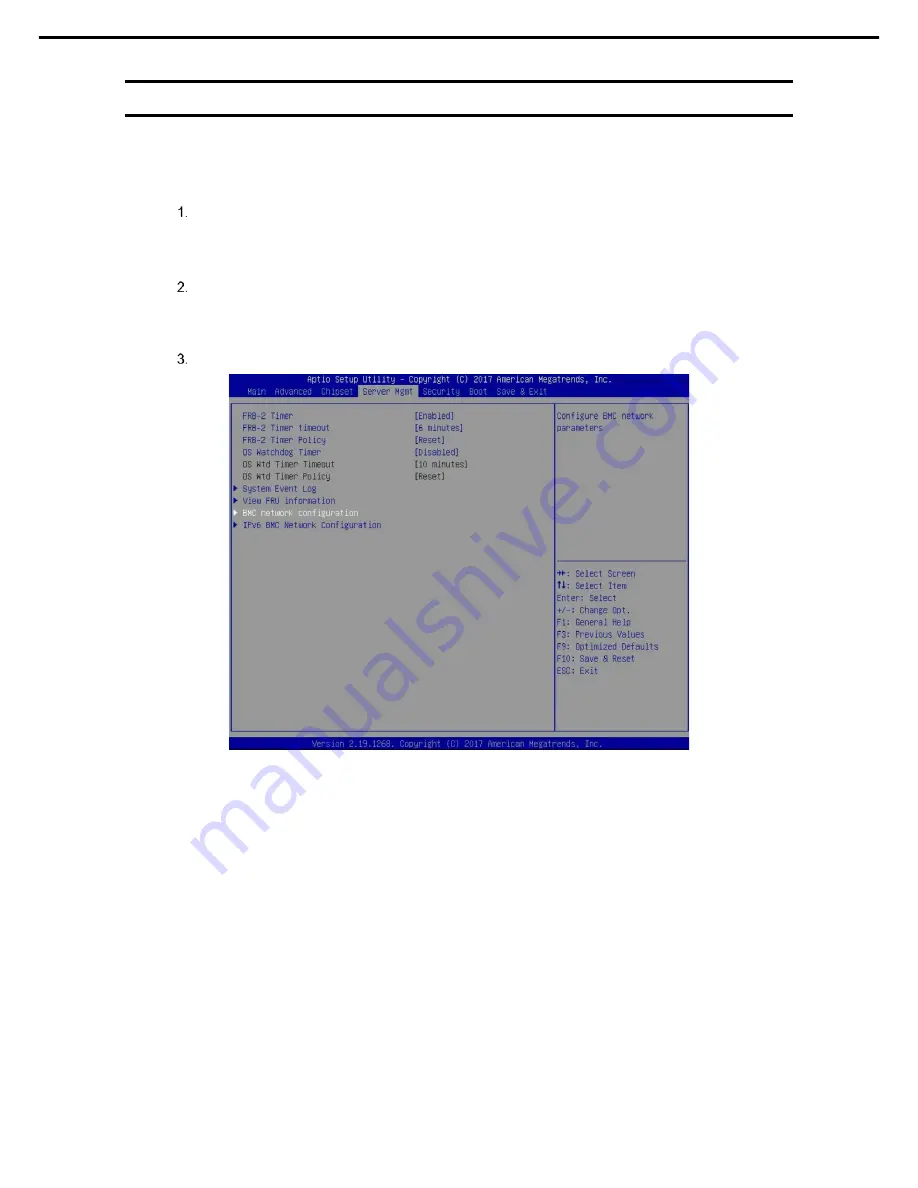
Select
Server Mgmt
→
BMC Network configuration
.


