


Welcome. . .
Thank you for buying an
IBM xSeries server.
This server
contains information for setting
up and configuring your server.
For detailed information about
your server, view the publications
on the
You can also find the most
current information about your
server on the IBM Web site at:
http://www.ibm.com/pc/support
Your server
is based on the X-Architecture
technology, and it features
superior performance, availability,
and scalability.
Documentation CD.
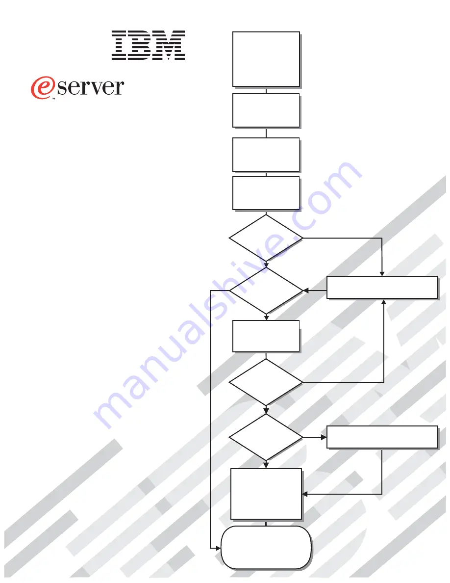
Installation Guide
Go to the Server Support
flow chart
Cable the server
and options
Start the server
Install options,
if required
• Drives
• Microprocessors
• Adapters
• Memory
Did the server
start correctly?
Yes
No
Use ServerGuide to
set up and
configure hardware
Did configuration
complete?
Is the Server
preconfigured?
Use
ServerGuide to
install operating
system?
Install applications,
such as IBM systems
management software
and IBM ServeRAID
programs
System is ready to use.
Go to the Server Support
flow chart to register
and profile your server.
Go to the Web for instructions,
http://www.ibm.com/pc/support
No
Yes
Yes
Yes
No
No
Installation Guide
Install the server in
the rack cabinet,
if required
xSeries 440
Type 8687
Summary of Contents for eserver xSeries 440
Page 3: ...IBM xSeries 440 Installation Guide SC59 P678 50...
Page 12: ...x xSeries 440 Installation Guide...
Page 20: ...8 xSeries 440 Installation Guide...
Page 56: ...44 xSeries 440 Installation Guide...
Page 72: ...60 xSeries 440 Installation Guide...
Page 86: ...74 xSeries 440 Installation Guide...
Page 95: ...Index 83 compatible options 20 25 working inside server with power on 6...
Page 96: ......
Page 97: ...IBM Part Number 59P6785 Printed in U S A 59P6785...


