MSI K9ND Speedster, User Manual
The MSI K9ND Speedster is a feature-packed motherboard that delivers powerful performance and reliability. Maximize your gaming and computing experience with this exceptional product. Complete your setup by accessing the comprehensive User Manual, available for free download from manualshive.com. Effortlessly fine-tune your system and unleash its full potential.
Share
Download


Reviews:
No comments
Related manuals for K9ND Speedster

315
Brand: IBM Pages: 151

ARX-2500
Brand: F5 Pages: 2

WANJet 400 Appliance
Brand: F5 Pages: 11

FT77B-B7059
Brand: TYAN Pages: 170

G.I. Joe Mission: Cobra HQ Game
Brand: Hasbro Pages: 3

S3116-NAS
Brand: Rackable Systems Pages: 4

Musiteca
Brand: Pathos Acoustics Pages: 26

BACnet/IP Server-SUNWAYS
Brand: IntesisBox Pages: 5

H SERIES RS/6000
Brand: IBM Pages: 424

callpilot 1002rp
Brand: Avaya Pages: 150

PCA35A-R3
Brand: Black Box Pages: 30

SUPERSERVER 1018D-73MTF
Brand: Supero Pages: 124

PUZZLE-IN004 Series
Brand: IEI Technology Pages: 102
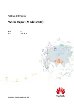
2180
Brand: Huawei Pages: 39

3010
Brand: Huawei Pages: 188

5288 V3 V100R003
Brand: Huawei Pages: 297

1288H V5
Brand: Huawei Pages: 2

SUPERSERVER 6113L-8
Brand: Supero Pages: 104


