background image

Order 

toll-free

in the U.S. 24 hours, 7 A.M. Monday to midnight Friday: 

877-877-BBOX

FREE technical support, 24 hours a day, 7 days a week: Call 

724-746-5500

or fax 

724-746-0746

Mail order:  

Black Box Corporation

, 1000 Park Drive, Lawrence, PA 15055-1018

Web site: 

www.blackbox.com

•   E-mail: 

[email protected]

CUSTOMER 

SUPPORT

INFORMATION

APRIL 1999

PCA35A-R3

PCA35AE-R2

PS035A

PS034E

PQ-6 PLUS (RO)

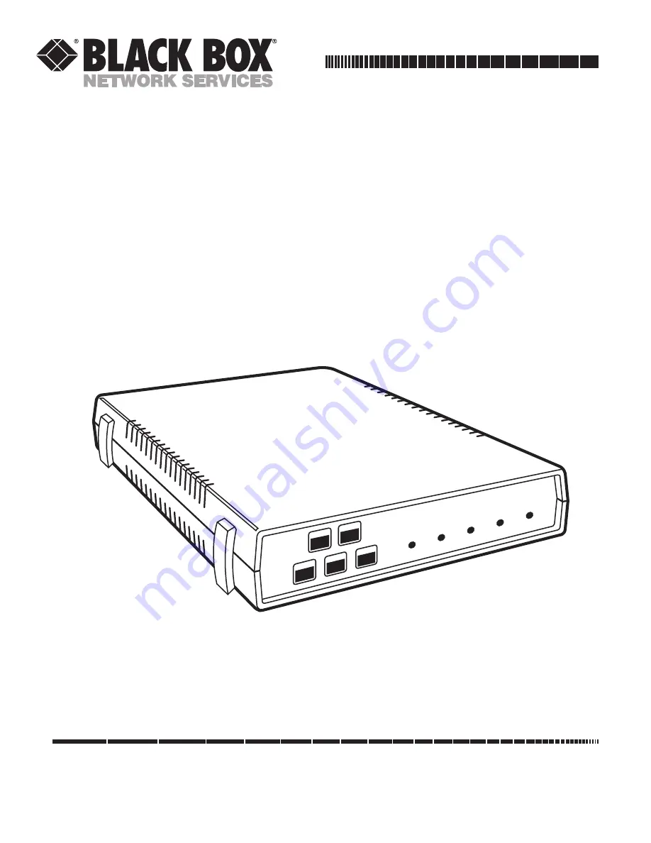
Receive-only printer interface for IBM

®

System 3X and AS/400

LINE

SYNC

DTR

DATA

OUT

TEST

PWR

PQ-6 Plus (RO)

START

STOP

TEST

LF

FF

Summary of Contents for PCA35A-R3

Page 1: ... fax 724 746 0746 Mail order Black Box Corporation 1000 Park Drive Lawrence PA 15055 1018 Web site www blackbox com E mail info blackbox com CUSTOMER SUPPORT INFORMATION APRIL 1999 PCA35A R3 PCA35AE R2 PS035A PS034E PQ 6 PLUS RO Receive only printer interface for IBM System 3X and AS 400 LINE SYNC DTR DATA OUT TEST PWR PQ 6 Plus RO START STOP TEST LF FF ...

Page 2: ...erated in a commercial environment Operation of this equipment in a residential area is likely to cause interference in which case the user at his own expense will be required to take whatever measures may be necessary to correct the interference Changes or modifications not expressly approved by the party responsible for compliance could void the user s authority to operate the equipment This dig...

Page 3: ...ire por los orificios de ventilación 10 El equipo eléctrico deber ser situado fuera del alcance de fuentes de calor como radiadores registros de calor estufas u otros aparatos incluyendo amplificadores que producen calor 11 El aparato eléctrico deberá ser connectado a una fuente de poder sólo del tipo descrito en el instructivo de operación o como se indique en el aparato 12 Precaución debe ser to...

Page 4: ...PQ 6 PLUS RO 3 TRADEMARKS The trademarks mentioned in this manual are the sole property of their owners ...

Page 5: ... RO Address Selection 15 3 2 2 System Configuration Reset 15 3 2 3 Printer Codes for Pitch and Density 16 3 3 Placing the PQ 6 in Operation 16 4 Operation 18 4 1 Operator Controls and Indicators 18 4 1 1 Function Switches 18 4 1 2 Indicator Lights 19 4 2 Setup Mode 19 4 3 Command Pass Through 21 4 4 Buffer Print Mode 22 4 4 1 Printout Format 22 4 4 2 Data Interpretation 22 4 4 3 Notes 23 4 5 Funct...

Page 6: ...le with twinax V 1 DB25 female Indicators 5 LEDs DTR Line Sync Power Test Data Out Temperature Operating 40 to 100 F 5 to 42 C Storage 40 to 140 F 40 to 60 C Humidity 0 to 95 noncondensing MTBF 50 000 hours Power PCA35A R2 115 VAC 60 Hz wallmount transformer part number PS035A PCA35AE R2 230 VAC 50 Hz part number PS034E Size PCA35A R3 PCA35AE R2 2 1 H x 8 8 W x 11 5 D 5 3 x 22 4 x 29 2 cm Weight P...

Page 7: ...gth characters per inch and horizontal and vertical carriage positioning sequences The PQ 6 PLUS RO interprets these command sequences and outputs ASCII characters to perform the appropriate function For example when a form length command is received the value is stored internally in the PQ 6 PLUS RO when it receives a request for a form feed or for an absolute move to line one of the next page th...

Page 8: ...smission of these data bits is controlled by the computer supplied STROBE pulse Handshaking flow control is achieved by asserting or deasserting either the ACKNLG or BUSY signal from the printer Figure 2 1 Typical Application S 3X AS 400 or remote controller PQ 6 PLUS RO Printer ASCII data serial or parallel Twinaxial Serial EBCDIC data and commands 1 MHz bit rate ...

Page 9: ...de setting the device address and all corresponding physical connections Section 3 3 Placing the PQ 6 PLUS RO into Operation details online testing procedures that you should implement after completely installing the unit This section also contains recovery procedures that you can use if the PQ 6 PLUS RO malfunctions 3 1 Initial Setup 3 1 1 INSTALLING A SUPPORTED PRINTER CAUTION Connecting a devic...

Page 10: ...PQ 6 PLUS RO 9 Figure 3 1 Board Layout Reset Power DB25 Female DB15 Male Serial Parallel 5 Ground EPROM Test Data Out DTR Line Sync Power ON SW1 1 2 3 4 5 6 7 8 1 2 3 4 5 6 7 8 SW2 ...

Page 11: ...F OFF OFF 1800 ON OFF OFF ON 2000 ON OFF ON OFF 2400 ON OFF ON ON 3600 ON ON OFF OFF 4800 ON ON OFF ON 7200 ON ON ON OFF 9600 ON ON ON ON 19200 Select the port configuration for RS 232 serial operation by setting Opt 3 to the ON position Place the large internal jumper strip on P3 P2 on boards with revision levels below C in the B C position to select RS 232 output Make sure that the cable to the ...

Page 12: ... 7 Data 6 PQ 6 PLUS RO 8 Data 7 PQ 6 PLUS RO 9 Data 8 PQ 6 PLUS RO 10 Acknlg Printer Indicates data received and ready to accept other data 11 Busy Printer Indicates printer cannot receive data 12 Paper End Printer Indicates out of paper 13 Select Printer Indicates printer is selected and ready to receive data 14 Auto Feed PQ 6 PLUS RO When this signal is low Jumper J1 the paper is automatically f...

Page 13: ...ug the PQ 6 RO PLUS Power and DTR indicators Proper response No corrective power supply into the AC line action is necessary No response on power or Power supply not plugged into back DTR indicators connector of the PQ 6 RO or no AC line power or PQ 6 RO power supply is defective DTR indicator blinking If configured for serial The attached serial device is not providing Data Terminal Ready DTR on ...

Page 14: ...n 1 Proper response No and printer are ON performing the occurs as described corrective action necessary and the Power ON self test via switches above test has been or via the front panel conducted test button successfully Switch method Set SW2 4 ON SW2 5 ON then press and release the reset button on the rear of the unit Front panel method Press the front panel test button When performing either m...

Page 15: ...CDEFGHI JKLMNOPQR abcdefghijklmnopqr stuvwxyz ABCDEFGHI JKLMNOPQR abcdefghijklmnopqr stuvwxyz ABCDEFGHI JKLMNOPQR abcdefghijklmnopqr stuvwxyz ABCDEFGHI JKLMNOPQR abcdefghijklmnopqr stuvwxyz ABCDEFGHI JKLMNOPQR abcdefghi jklmnopqr stuvwxyz ABCDEFGHI JKLMNOPQR abcdefghi jklmnopqr stuvwxyz ABCDEFGHI JKLMNOPQR abcdefghi jklmnopqr stuvwxyz ABCDEFGHI JKLMNOPQR abcdefghi jklmnopqr stuvwxyz ABCDEFGHI JKLM...

Page 16: ... address zero to six can be represented by an appropriate on off configuration of the switches Examples are given in Table 3 6 Table 3 6 Printer Options Address Selection DIP Switch Device Address Decimal SW6 ADR4 SW7 ADR2 SW 8 ADR1 0 OFF OFF OFF 1 OFF OFF ON 2 OFF ON OFF 3 OFF ON ON 4 ON OFF OFF 5 ON OFF ON 6 ON ON OFF 7 ON ON ON ON ILLEGAL 3 2 2 SYSTEM CONFIGURATION REQUEST Physically the PQ 6 P...

Page 17: ...ed ASCII printers You can find the list of printers on page 20 3 3 Placing the PQ 6 in Operation When notified that the system operator has completed the system configuration you can power on the PQ 6 PLUS RO and all other cabled through devices using the following procedure A Plug the power supply into the AC line B Place the AC power switch on the attached printer in the ON position and place th...

Page 18: ... condition or switches and P2 jumper not in proper position Head moving printing No ribbon Install new ribbon Defective ribbon Install new ribbon No printing in test mode Ribbon out Install new ribbon Paper out Install forms Printer AC off Turn on printer power No DTR or select from printer Check cables and printer power Test message printed Incorrect PQ 6 RO baud rate Set correct baud rate via sw...

Page 19: ...e one line for each key you press The internal line counter will also be advanced For continuous line feeds hold this switch ON Form Feed Pressing the FORM FEED switch will cause the paper to move to the top of the next form Stop Pressing the STOP switch stops printing on the PQ 6 PLUS RO Plus It also presents unit not available status to the controller The message press start on printer Pn will a...

Page 20: ...f internal switch and jumper settings for baud rate printer interface etc must have been done previously See Section 3 1 4 2 Setup Mode You can configure the PQ 6 s twinax address printer emulated ASCII printer type page select and command pass through by the front panel or the internal DIP switches NOTE ASCII printer type is only selectable via the front panel To enable configuration via the fron...

Page 21: ...inter attached is NEC SpWr 3500 Current printer attached is FX 80 Press FF to save configuration Press STOP to cancel configuration SELECTING SWITCH SETTINGS This mode lets you change the initial switch settings using the front panel instead of removing the top cover of the PQ 6 PLUS Follow the instructions on the printed menu to select the different switch selections Upon exiting this mode the sw...

Page 22: ...it binary value from Hex 00 to Hex FF The PQ 6 does not interpret or translate data when in command pass through mode To enter command pass through mode send the two character sequence ampersand percent as part of the normal printable data NOTE Ampersand EBCDIC 50 Hex Percent EBCDIC 6C Hex After it enters command pass through mode the PQ 6 PLUS RO takes characters from its internal print buffer an...

Page 23: ...ne or two groups of three lines At the beginning of each block of data a new group of three lines starts Thus the position of the data within each block can be readily seen Take care here if you re using a printer that will print only 80 character lines The groups of three lines are up to 128 characters long If the printer used will only print 80 character lines or has been set to print only 80 ch...

Page 24: ...ts the printer into the international character set The 2B C1 is for setting the maximum print position 02 again states that 2 bytes follow the 2BC1 command and 84 is hex for 132 Thus it sets the maximum print position to 132 The 2B C2 sets the maximum number of print lines per page 02 42 specifies two following bytes and sets it to 66 lines per page The 2B C8 states what the printer will do when ...

Page 25: ...ssthrough 4 OPT1 OFF Use FF Form Feed character for page eject ON Use Multiple Line Feed for page eject Table 4 2 Option Switch SW2 Switch Bank 2 Position Function 1 2 Printer type select 00 5256 01 5224 10 5225 11 illegal 3 Parallel Print option OFF PQ 6 responds to the busy and acknowledge signals from the printer ON PQ 6 responds to the busy signal only This setting increases the data transfer ...

Page 26: ...ckspace 0C 0C Form Feed 00 00 Carriage Return 0F 20 15 0A Line Feed 16 08 Backspace 25 0A Line Feed 2F 07 Bel 40 20 Space 46 20 Carriage Return 47 20 Line Feed 48 20 Form Feed 49 20 Line Feed 4B 2E 4C 3C 4D 28 4E 2B 4F 7C 50 26 5A 21 5B 24 5C 2A 5D 29 5E 3B 5F 5E 60 2D 61 2F 6A 7C 6B 2C 6C 25 6D 5F _ 6E 3E 6F 3F 79 60 7A 3A 7B 23 7C 40 ...

Page 27: ... 65 e 86 66 f 87 67 g 88 68 h 89 69 i 91 6A j 92 6B k 93 6C l 94 6D m 95 6E n 96 6F o 97 70 p 98 71 q 99 72 r A1 7E A2 73 s A3 74 t A4 75 u A5 76 v A6 77 w A7 78 x A8 79 y A9 7A z C0 7B C1 41 A C2 42 B C3 43 C C4 44 D C5 45 E C6 46 F C7 47 G C8 48 H C9 49 I D0 7P D1 4A J D2 4B K D3 4C L D4 4D M D5 4E N ...

Page 28: ... DESCRIPTION D6 4F O D7 50 P D8 51 Q E9 52 R E0 5C E2 53 S E3 54 T E4 55 U E5 56 V E6 57 W E7 58 X E8 59 Y E9 5A Z F0 30 0 F1 31 1 F2 32 2 F3 33 3 F4 34 4 F5 35 5 F6 36 6 F7 37 7 F8 38 8 F9 39 9 NOTE Any characters not shown are not used ...

Page 29: ...ype select 00 5256 01 5224 10 5225 11 illegal 3 Parallel Print option OFF PQ 6 responds to the busy and acknowledge signals from the printer ON PQ 6 responds to the busy signal only This setting increases the data transfer rate to the printer 4 Configuration option ON DIP switch OFF Front panel 5 Self Test 6 7 8 Address select 0 6 0 OFF 1 ON PQ 6 RO Board Layout Baud Rate Switch Baud Rate S5 S6 S7...

Page 30: ...1000 Park Drive Lawrence PA 15055 1018 724 746 5500 Fax 724 746 0746 Copyright 1999 Black Box Corporation All rights reserved ...

Reviews: